Introduction
With evonHOME, you have brought the most up-to-date home automation system into your home. We want to help you with the planning so that your project is easily implemented. Before you dedicate yourself to the detailed information in the documentation, we would like to give you a rough overview of the functionality in an evonHOME system.
Depending on what you intend to control, you will need different evonHOME modules (light module, blinds module …); according to the application or function, there is a range of different modules you can choose from. The autonomous evonHOME modules provide you with centralized functions such as “All Lights Off”. The complete range of control functionality is only available with the CPU module, which enables the configuration and control to be done via smartphone, tablet or PC.
The modules are mounted in one or more cabinets and need to be connected and wired differently to conventional electrical installations. The electrical consumers are connected to the module outputs and one or more switches are connected to the inputs. In contrast to a conventional electrical installation, the switches are not used to directly switch 230V to a consumer, but to control an evonHOME module. Since the laying of empty conduit and the laying of cables occurs at a different time to the installation of the consumer unit and the commissioning of the controls, it is extremely important that the cabling for electrical consumers and switches is planned in detail. Hence the first part of our documentation details with the necessary steps to do this.
Before Installing
Here you will find all necessary information about the installation of your evonHOME.
Planning
You need to consider a few things when implementing your smart home project. If you want, you can determine the following points yourself and go to an evonHOME partner of your choice with the results, or the evonHOME partner can accompany you and advise you through these steps.
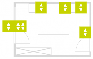
In the beginning, there was a plan – what do I want my house to be capable of? Take your house plans and think of the following for each floor and room:
- Where will the consumer unit be located?
- Number of electric blinds and what type (standard or 24V with reverse switching?).
- Number of separate switchable light circuits and what type (standard via load relay, integrated load relay or dimmer function).
- Number of room temperature regions for temperature control (number of heating circuits per room temperature region is not relevant here).
- Number of special functions via input and outputs (e.g. doorbell, alarm light, window contacts, presence sensor, camera, audio, …).
Shoppingcart
First things first: think about what you actually want to control. Don’t worry at this stage about how and when, because all functions can be combined later via the evonHOME app. Just get them connected to the controller (lights, blinds, garden irrigation, doorbell, …).
The evonHOME configuration Excel file enables you to determine your exact module requirements and helps you keep an eye on the costs.
You will need a 24V power supply for the modules and a CPU evonHOME Controller (HC-iX800) module for the app control.
Example:
Let’s take a bedroom on the first floor as an example. We will use this example throughout the entire documentation and show the full capability so that we can use it everywhere.
Electrical Cabinet Placement
Depending on space requirements and availability, you can install everything in a central consumer unit or split it up over sub-consumer units. Normally, it is advantageous to combine the cellar, ground floor and outdoors area in a single consumer unit and put the electronics for the first floor in a smaller sub-consumer unit on the first floor. Using sub-consumer units reduces the length of cables and thus substantially reduces the cabling effort and simplifies the feeding in of cables.
You will need a bus extension module for every sub-consumer unit to connect the evonHOME modules to one another. You also need a bus extension module (Sys 1200) each time you start a new row within a consumer unit.
A separate 24 V supply is not always required for a sub-consumer unit. If the power is sufficient, you can route the supply from a previous unit.
Ensure that the GND connection of all power supplies is connected with the protected earth connection (PE).

Example:
Since the bedroom is on the first floor, we will use a sub-consumer unit. The power supply and the evonHOME controller are placed into the main consumer unit and the bus extension and the module for the bedroom in the sub-consumer unit. Both consumer units are connected to each other with the bus cable (CAT5) and the 24V power supply cable.
Blinds
The number and type of blinds to be controlled determines which module is to be used. It doesn’t matter whether the shading element is a roller shade, internal blinds, external blinds, or an awning – the important thing is how it is driven. Use the evonHOME module Blinds module B1144 if the motor has a separate line for UP and DOWN and is supplied with 230V. If the motor has a reversing switch then use the evonHOME module Blinds module B1244. Each of these modules can control two shading elements.

Example:
The bedroom has a window and a balcony door whose shading elements are to be controlled. Both shading elements are equipped with a normal motor (UP/DOWN, 230V). We will therefore plan an evonHOME module B1144, whereby the first output will be used for the balcony door and the second output for the window.
Light Circuit
It is important that you consider the number, function and type of lighting you wish to use for illumination. It is a good idea to draw your lighting circuits on a floor plan and note whether the circuits should be switchable or dimmable. Once you have considered the lighting circuits, the next thing to think about is the type and number of lights per lighting circuit: they will determine the optimum module selection:
The dimmable light will need the evonHOME dimmer module L1424. Each module can control 2 lighting circuits. In addition to the dimmer modules, you will need a dimmer pack for each dimmable light suitable for your type of bulb, for example the Eltako SUD12 1-10 V universal dimmer switch. The evonHOME dimmer module L1424 controls the dimmer pack via 0-10V or 1-10V; you can switch your dimmer pack or an intermediate relay on or off via the digital output of the dimmer module. Two dimmer circuits can be connected to each module.
The other lights will either require the evonHOME lighting module L1244 with integrated 230V/16A relay or the evonHOME lighting module L1144 to connect external relays for larger loads. You can choose either, or ask your electrician to decide for you. Four lighting circuits can be connected to each module.

Example:
Two normal and two dimmable lighting circuits are to be installed in the bedroom.
Both of the normal lighting circuits are used for the ceiling and balcony lighting; an evonHOME module L1244 (with 16A relays) is sufficient here. Only two of the four outputs of the lighting module are used, the other outputs can and should be used for other rooms.
The two dimmable lighting circuits are reserved for two reading lights positioned left and right of the bed; they will use an evonHOME dimmer module L1424. In addition, we will use a dimmer pack each, which will be connected later to the modules.
Temperature Control
To control temperature, you will need the evonHOME single room modules C1144 or C1244. Module C1144 is controlled by the evonHOME room operating panel and module C1244 via PT1000 sensors, or from an external demand value (for example from an analog input).
Four control valves and 4 room operating panels can be connected to the evonHOME single room control module C1144 and C1244, whereby this corresponds to 4 separate room control zones. Each output can be connected to as many valve drives in parallel as you wish; it is only limited by the load on the relay output. This is useful if you have to install several heating circuits in a room because of the heating pipe lengths and the room is to remain a single zone with a constant temperature distribution.
You still need temperature sensors in the rooms with module C1144 so that the controller can modify the temperature as required. Temperature sensors are already integrated into our room operating panels C1101, C1102, C1103 and C1104. When fully equipped, in addition to room temperature measurement, the models C1101 to C1104 also have other functions such as demand temperature selection, mode selector (comfort, energy-saving, frost protection) and presence button (raise/lower temperature when activated).
In contrast to module C1144, the temperature demand value and mode cannot be changed with module C1244, this is only possible via the App, since only a PT1000 temperature sensor can be connected to the input of module C1244.

Example:
Naturally, we also want to control the climate in the bedroom. There is a heating circuit in the bedroom. We select the room-operating panel C1103 (temperature sensor, demand value, mode setting and presence button), the choice is yours.
We need an evonHOME single room module C1144 for the heating circuit, whereby the valve requires an output leaving three outputs free.
Special Functions
Special functions such as doorbell, door opener, window contacts, garden irrigation, scene buttons etc. require our digital modules. To determine how many modules you need, consider first the number and type of special functions you require. The evonHOME digital module D1180 has 8 digital inputs at 24V DC and is normally used in conjunction with the evonHOME digital module D1208, which has 8 digital outputs. The evonHOME digital module D1344 combines 4 inputs and 4 outputs in one module.
The inputs are designed for 24 V DS for all modules. Make sure you never connect higher voltages or alternating current sources to the module; otherwise it will be irreparably damaged.
The outputs can be used, depending on the wiring, to switch either 24 VDC or 230 V AC, however note when using 230 V consumers, the load is ohmic and may not exceed 5 A! Ohmic loads are, for example, normal light bulbs, whereby LED lamps represent capacitive loads and must be switched using an external relay. If in doubt, please ask your electrician or evonHOME partner!

Example:
Using our bedroom example, we plan to add an alarm system and we need a digital input and a switch to activate and deactivate the alarm, and a closing contact for the window and balcony door.
We plan an evonHOME digital module D1180 with 8 digital inputs, whereby 4 inputs are for the bedroom (the 4 reserve inputs can be used for a further room). Two inputs are for the closing contacts and two others for the switch.
In our example, we demonstrate the planning of special functions via digital modules.
Switches
Basically, you have a free choice concerning the switch type, but for evonHOME, we only use pushbuttons. We recommend that you use pushbuttons with at least 2 to 4 pushbutton functions per unit (corresponding to a flush-mounted socket). Since evonHOME only switches 24V signals via the pushbuttons/ sensors, there are no particular requirements concerning current carrying ability.
Example:
In our example, we plan using the following switches:
- 1x 2-way pushbutton at the entrance for the ceiling light, a double-click switches the dimmable reading lights and the ceiling light off.
- 1x 4-way and 1x 2-way pushbutton next to the balcony door. Two pushbuttons each for the two window shades UP / DOWN, one for the external light and one for the ceiling light.
- 2x 2-way pushbuttons, one of each side of the bed. 1 pushbutton for the dimmable light and 1 for the ceiling light.
- 1x 2-way pushbutton behind the bed for special functions, this could normally be handled with a double-click or a long push and are only in our example to demonstrate the evonHOME digital module D1180.
Control Cabinet
Once you have decided the number of evonHOME modules, relays and pushbuttons and have also fixed how you wish to distribute them in the cabinet(s), you can dimension the consumer unit. Basically, you can install evonHOME in any standard consumer unit due to the standard rail mounting with 45mm plate.
All lights, blinds and other loads, all switches, window contacts and sensors are wired into the appropriate consumer unit. For the switches, we recommend the use of multi-core communication cable (F-YAY) or CAT5 cable. Clearly arrange them, optimally on LSA plus strip (see template connection strip).
Do not forget to leave space for the power supply, bus extension and bus terminator. Once everything has been installed, 20-30% of the space in the consumer unit should be free for future extensions.
Example:
In our bedroom example, we have planned a sub-consumer unit for the modules on the first floor.
The total space requirements for the sub-consumer unit on the first floor results from: 176mm in the first row and 132mm in the second row – including bus extension for row extension and bus terminator.
First row:
- 0x power supply: power is supplied from the main consumer unit
- 1x evonHOME bus extension: 22mm
- 1x evonHOME blind module B1144: 44mm
- 1x evonHOME lighting module B1233: 44mm
- 1x evonHOME dimmer module L1424: 44mm
- 1x evonHOME bus extension: 22mm (to new row)
Second row:
- 1x evonHOME bus extension (new row)
- 1x evonHOME single room control module C1144: 44mm
- 1x evonHOME digital module D1180: 44mm
- 1x evonHOME bus terminator: 22mm
We need additional space for several circuit breakers and for a suitable LSA Plus strip to connect the pushbuttons (4x 24V supply, 13x pushbutton inputs).
Cabling
All cables must be routed to the consumer unit in which you have planned the corresponding module.
Each button will require a 24V voltage supply (+24V), and per pushbutton a cable that is connected to the pushbutton and the corresponding module. When cabling the sensors (pushbutton, contact, room operating panel) we recommend the use of communication cable (F-YAY) or CAT5 cables. If you wish to have more than one pushbuttons connected to a module input, you can either daisy-chain the cable in the room (from switch to switch, contact in the junction box) or cable all switches to the consumer unit and connect them all together there. The second variant gives you the advantage to only have the connection effort once, in the consumer unit, but increases the effort required for initial installation and cabling, and more space requirements in the consumer box.
Use deeper junction boxes as switch back boxes or boxes with more space – you will be grateful to yourself later when it comes to connecting the cables.
As opposed to a conventional electrical installation, the switches do not come into contact with the 230 V mains, however 230 V mains supply must still be routed into the consumer boxes to be connected to the evonHOME modules to provide power for the consumers (lighting circuits, blinds…).
Make sure that you do not forget cables for the room control unit, doorbell, window contacts, door opener etc. It is better to route one cable more than necessary than have one too few.
Wiring
The consumer unit houses the mains connectors, LSA Plus strips, evonHOME modules, their supply, further relays and, if necessary, the circuit breakers for the 230V circuits.
The 24 V power supply and the pushbutton and sensor inputs – i.e. the CAT5 or communication cable – are connected to an LSA Plus strip and wired from there to the evonHOME modules.
The 230 V cables are wired via terminal strips or directly to the evonHOME modules or load relay.
More information on how each module is connected individually can be found in the module description or a wiring diagram is printed on the side of each module. The individual wires can be easily allocated using the connection list and the cable labels.
If you are unsure, please contact your evonHOME partner or an electrician.
Electrical connection work may only be carried out with the power disconnected and only then by suitably qualified expert staff.
CPU I/O
You can connect up to four digital inputs and two digital outputs to the evonHOME controller (iX800).
Some of these In- and Outputs are already assigned with predefined functions (rain, storm, ...) - the assignment can always be changed by the user.
DI1
Digital Input 1 – Predefined as Home Off - Switch
DI2
Digital Input 2 – Predefined for rain detection
DI3
Digital Input 3 – Predefined for twilight detection
DI4
Digital Input 4 - Predefined for storm detection
DO1
Digital Output for arbitrary use
DO2
Digital Output for arbitrary use
These In- and Outputs can be found in the Hardware-App by clicking on the left Area of SC1-Line1 (smartCOM Line1).
General
Your new evonHOME can be controlled either conventionally via the pushbuttons mounted on the wall, or also via your PC, tablet or your smartphone. This way, you have your evonHOME with you all the time. You have full access to all functions that make your life easier, from your sofa or when you are traveling.
Connecting
In order to be able to control your home via the app, your must first connect to your system. Simply follow these simple steps.
WiFi Connection

Before your activate your evonHOME app, make sure you are connected to the same network as your evonHOME controller. Simply go to the WLAN settings on your device and check the currently selected WLAN, or connect to the correct one.
In case you switch on your evonHOME CPU for the first time and it does not receive a valid IP address after several attempts (DHCP), it will automatically switch to the following static address:
IP-address: 192.168.50.50
Subnetmask: 255.255.0.0
Home Screen

Once you have successfully installed the app via the AppStore, the app is located on the home screen. You can start the app directly from here. After a short time to load the app, you will see the start page of the app.
From here, search for the available evonHOME systems. The selection is either a connection via a local Wi-Fi/WLAN or the internet (e.g. mobile network provider via a secure HTTPS connection).
If you are configuring evonHOME for the first time, select “Wi-Fi” in order to search for your system via the local WLAN.
Start Search

The evonHOME app will now search for all system in your network. As soon as one or more have been found, they will be displayed along with their allocated IP address. Your new system will be listed with the default name evonHOME + unique identification number (e.g. evonHOME_1234AB9). You can change the name later, if your wish.
Once you have selected your evonHOME system, the next thing you must do is login.
Login

After selecting the evonHOME system, you will find yourself on the login page.
Enter your username and password. You can also determine whether you wish in future to login automatically with your login data.
To make it easier for you to login to your evonHOME on your first configuration, there is also the option to do this by using a QR-code. Use the green button on the top right corner of the login screen to use this feature.
Point the camera at the QR-code, which you will find in your enclosed documents, and position it at the center of the marked area. once the QR-code ist successfully recognized, the associated login field will be filled in.
You have now successfully connected to your evonHOME system and can start to control your home.
To connect for the first time, use the username and password or QR-code provided for you in the enclosed documents.
Browser

Besides accessing your evonHOME system with the official app, you can also connect to it with any modern browser (e.g. Chrome, Safari, Edge). You only have to know the IP-Adress (Which is displayed in the app once your system is found).
When you enter the address in the url bar of your browser, you will be directed to the login page, where you will have to enter your credentials. You can then use your evonHOME system like you are used to.
If you connect to your evonHOME system with a browser (e.g. Chrome), some device specific functions from the mobile App may not be available to you. These include, among others, native notifications, which also appear when the app is currently not in use.
External Access
If you are currently not at home, but would still like to have access to your home control, then you can use the external access provided by your evonHOME system. If you have activated this option, you can access your system from anywhere in the world assuming there is an Internet connection, just as if you were at home.
The configuration for external access is located under “all apps” – “settings”.
Configuration

Activate the function for external access in the settings by placing a tick next to it.
As soon as you have activated the function, the displayed status changes from “not connected” to “connected” and the evonHOME ID appears. This ID is required to connect you to your evonHOME system. It is a good idea to write this ID down, you will need it in the next step.
This evonHOME ID gives you the ability to access your system from a normal web browser (via
my.evon-home.com).
Logout

Return to the main screen. On the top left is your current username. If you click on it, the logout button will appear. Logout via this button.
You will now be on the start screen of the evonHOME app, which shows a list of all your previously connected systems.
Connect

Click on “new” to create a new connection. You will now see an overview of all possible connection types, as described previously.
Select “internet” as the connection type. You must enter the evonHOME ID in the next screen, along with your username and password. When done, connect via the button at the bottom of the screen.
As soon as you have successfully connected to your evonHOME system via the external connection, this connection will appear on the start page of your evonHOME app. You can now easily select this connection at any time.
The first external connection to your evonHOME system can take some time. Even once the connection has been established, please wait until all data has been uploaded before your quit the app.
Browser

Once you activate the external access, you can connect to your evonHOME system from every supported browser (Safari, Chrome, Edge).
Go to the website my.evon-home.com and login with your credentials. In addition to your user name and password, your will also require the evonHOME ID, which you received by activating the external access.
If you connect to your evonHOME system with a browser (e.g. Chrome), some device specific functions from the mobile App may not be available to you. These include, among others, native notifications, which also appear when the app is currently not in use.
Interface
Visualization of your evonHOME system enables you to control all functions in your home and adjust all necessary settings. There are a few simple concepts that we would like to describe here.
Current User

Once you have logged in, your username is displayed at the top left of the screen. Clicking on your username opens a menu where you can logout.
All Apps

A single click on the symbol (top right) opens all apps. This shows you all available apps. If you don’t want “all apps” open all the time, you can put frequently used apps into your favourites, as follows.
Favorites

Favourites lets you store apps that you use on a frequent basis.
If you want to add something to your favourites, mark the function (press the app with your finger/your cursor until a blue bar appears below) and select “add to start”.
If you want to remove something from your favourites, mark the app and select “remove from start”.
Areas

After the favourites are your areas. First up are your floors (ground floor and first floor in the diagram) and below that your areas and rooms. However, only those areas that contain something are displayed. For example, if a light is added to the room “bedroom”, the bedroom will be displayed.
Usage
Every app contains different views and representations that are used for opening, operating or changing settings.
App

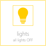
This is the basic representation of every app in the system. A single click/press on this display opens the app view and its functions can be used and/or changed.
App Interface

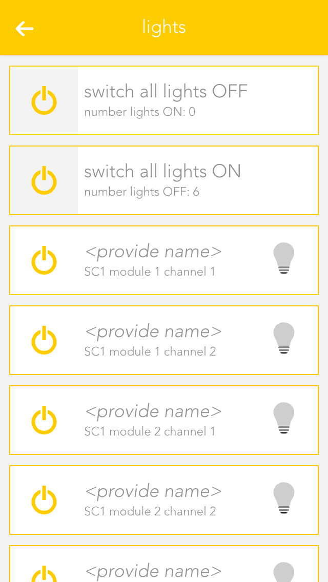
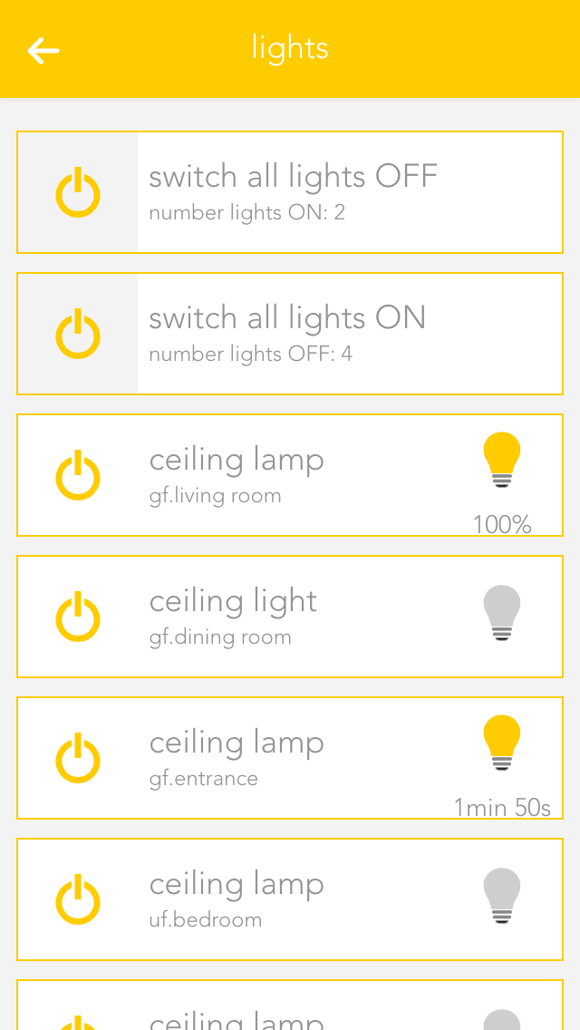
As long as you have an app open, you can also open its view. This shows you all content and functions that are available to you. In the case of the light app, the items displayed include all connected lights and the group functions.
Group Functions

The group function can vary from app to app, but is mainly used to create new elements or to operate several available elements. Taking the app “lights” as an example, it can be used to switch all available lights on or off. In other cases, such as “user”, you can add new users.
Elements

This display represents a single element in the app. In the case of “lights” every single one of your connected lights is displayed like this. The display is divided into several individual sections, each one serving a different purpose. The area on the left contains operating elements in the form of one or more buttons that you can use to control the element (e.g. light on/off). Then there is a text area containing information such as the name and the allocated area. On the right, many apps have a status display showing you the current status of the element. Fo lights, you can see whether the light is on or off, or (if the energy saving mode is active) when the light will be switched off.
Clicking /pressing the text area of an element opens the settings screen where you can change the app name, allocated areas and functions as you wish.
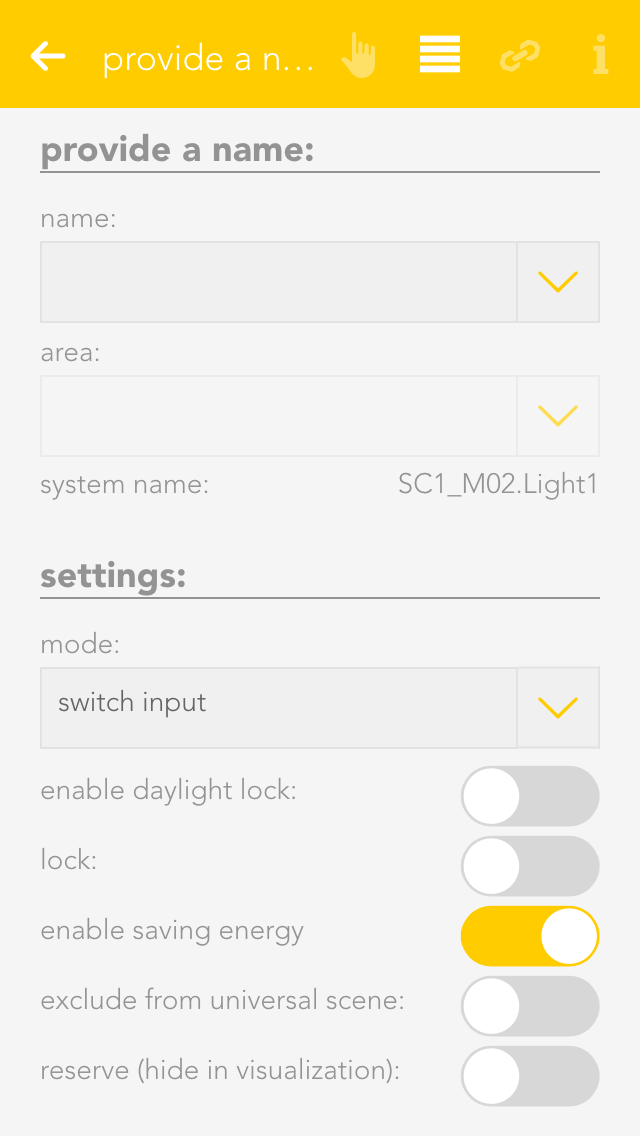
Settings

This display offers you various information and settings possibilities for the selected element and is divided into several sections. On the top right are small buttons that let you jump into other areas. The first section contains the most important operating elements via which you can operate the selected element and, depending on the app, various items of basic information.

The second section contains the settings that you can change for that element. These allow you to change the behaviour of individual element to suit your needs.

This section shows you al the links for your element. This gives you an overview, should you desire it, of which switches or functions affect the element. You can also link the element with other elements, depending on the app. For example, in the app “lights”, you have the possibility to link a light with a motion sensor.
In the settings view, most of the apps have a button on the top right allowing you to access the official documentation.
Please note that the settings possibilities vary from app to app and therefore not all sections are available for all apps.
Notifications
Your evonHOME uses a range of notifications to inform you of events in the system. For example, if you have integrated a door intercom, the system can notify you when someone rings the doorbell.

Depending on how you access your system, there are different forms of notification. If you access your evonHOME via an app or via a web browser, you will receive new notifications directly in the visualization. All collected and unread notifications can be found via the button “letter symbol” on the main page.
The evonHOME app, used on tablets and mobile phones, also offers you native system notifications. You will receive these even if you are not currently using the evonHOME app.
If you have started the evonHOME app for the first time, you will be asked if you would like to permit notifications to be sent to you. If you agree then the app will be able to send you notifications. You can change the settings for notifications for each individual device that accesses your system later in the app “devices”.
Configuration
Once you have connected the evonHOME app with your evonHOME, there are just a few steps to be taken in order to adapt your evonHOME to your requirements.
Areas
Use the app “areas” to organize your evonHOME into rooms and elements within the rooms (e.g. lights, blinds …). This way, you will be able to find them quickly.
Your previously defined rooms will be displayed on the home screen (as long as they contain elements). To modify the rooms, open the “settings” app and select “areas, rooms”.
Create
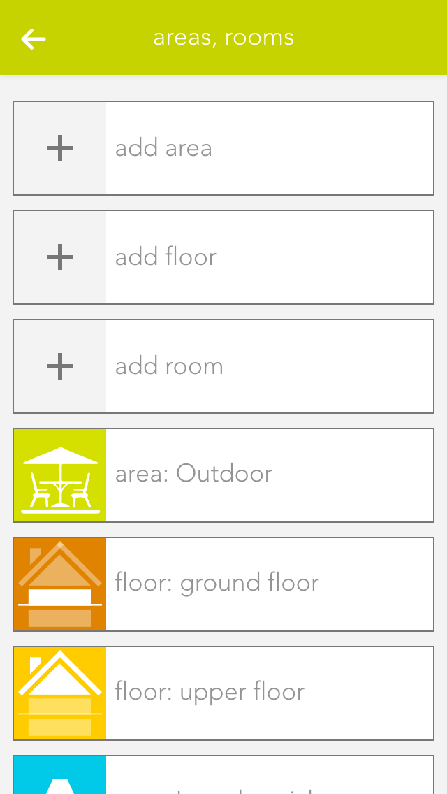
In order to add rooms, areas and floors to your evonHOME, simply tap on the corresponding element (e.g. “add room”). This automatically opens the operator panel for the added element. Enter the name into the field “name” and an abbreviation in the field “abbreviation” for the room. If you want to allocate this new room to a floor, simply select the floor you want. If you want to move the area back to the highest level, select the empty entry in “area, floors”.
Alternatively you can first navigate to a floor and add a room there.
Settings
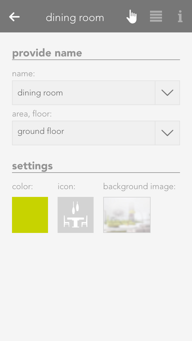
If you wish to personalize your rooms, you can select colour, icon and background picture for your room. Do this by opening the operator panel for the room via in “settings” – “areas, rooms” and select the element under “settings” and modify it.
Open the area via the button “edit” and view the elements for this area. If you want a shortcut to an area, simply click on the area of the symbol in the object panel (left).
You can also link each room with a room thermostat. Do this by allocating an element to this room in the app room climate. If you have allocated more than one room thermostat to a room, you can use the parameter panel of the room to select the room thermostat you wish to use for the room temperature display.
Naming
After you have connected via the evonHOME app to your evonHOME system, you should name all of the connected devices (lights, blinds, heating circuits, etc.) and allocate them to a room. This helps you to not only find and operate them easier, but also to access further functions.
Select
Open “lights”, “blinds” or “room climate”, depending on the items you wish to modify the names and rooms.
The app shows you a list of central functions and below that a list of your elements – this corresponds to the channels of your evonHOME modules. More detail concerning the central functions can be found in the corresponding documentation.
Tap on the area that displays the name and the room, in this case “ no name”, “no room” to open the settings for this device.
Provide Name and Room
Enter the name of the device in the field “name”. You can type any name in here, or use a predefined name by tapping on the small arrow.
Tap on the field to select a room. The system already has a predefined few names that you can use. If you cannot find a suitable room in the list, create one in the settings -> areas and custom rooms.
You do not need to specifically save your changes, simply tap on the arrow symbol in the menu bar.
Choose a distinctive name depending on the device and purpose like: ceiling light, ambient, radiator or wall heating.
User & Groups
You can allocate different rights in your evonHOME to users, for example so that children can only use functions in the children’s room. The rights are controlled via the user groups.
You can find users and user groups in “all apps” – “settings”.
User
A user allows you to control exactly the rights for your evonHOME.
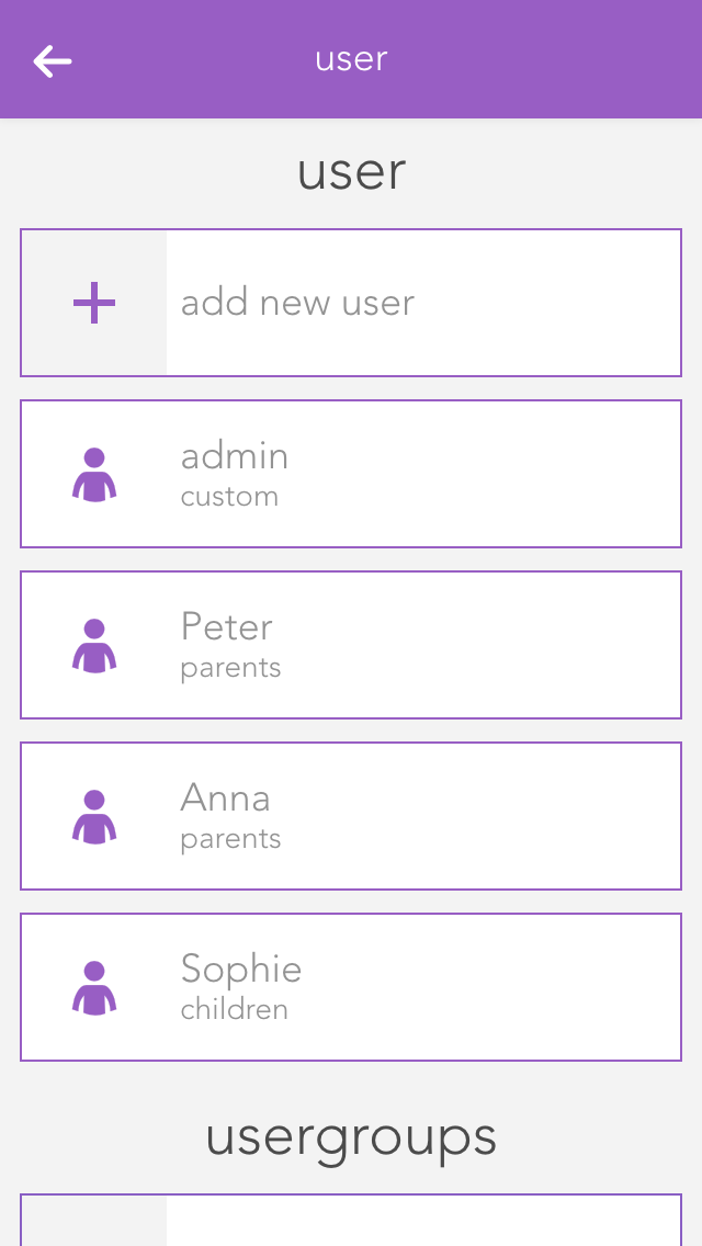
You can add a new user here or configure an existing one. To add a new user, simply select “add user”. This opens a panel where you can enter the user name and an optional description. Enter a password for the user so that you can login using the username.
Settings
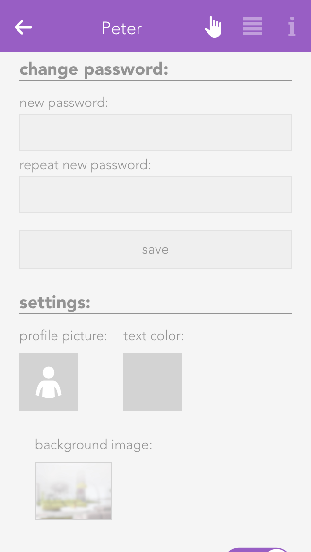
Profile picture
The profile picture to be displayed for this user.
Background picture and text colour
You change the background of your visualization as you wish. The text colour selects the colour of titles such as “favourites” on the home screen so that they are readable, even with other background pictures.
Show areas on the home screen
This setting lets you define whether areas will be displayed on this user’s home screen.
Own favourites
If you activate the option “own favourites”, you can customize the favourites on your own home screen without these changes being visible to other users. If this option is deactivated, then your favourites are shared with other users and any changes will be visible to all users.
Language
This lets you change the language for this user. To change the language of the current user, click on “load new language settings”.
Permissions
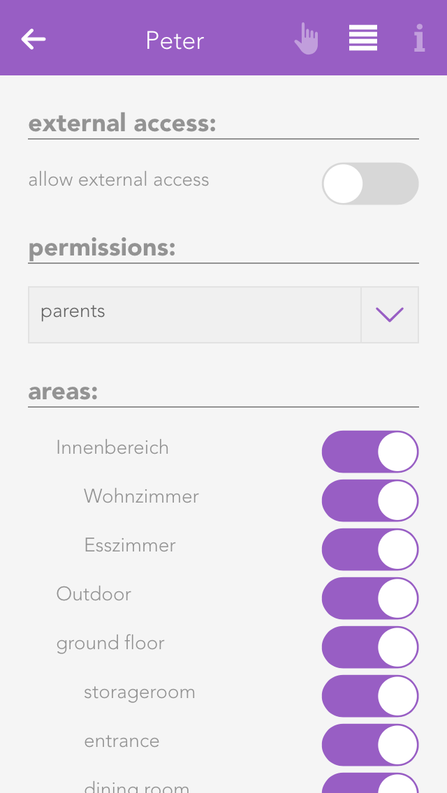
Permit external access
The option “allow external access” lets you decide whether this user is permitted to connect to your evonHOME externally.
Rights
This allows you to allocate rights to this user. If you want to allocate rights independently from a group, simply select “user defined”. The individual rights are explained further down the screen. If the user is to have no rights, simply select “no rights”.
Areas
The section “areas” lets you select which the areas this user is to have access to. If you have allocated this user to a user group, the rights in this group have already been defined for this area and hence you only have the possibility to limit the rights for individual areas further.
Some changes cannot be made to the user you have used for your login. So for example you cannot withdraw administrator rights or delete the current user.
Groups
User groups allow you to configure rights for several users.

The settings can be modified for a user group that already exists, or a new one can be created. To create a new user group, click on the element “add group”. This opens a panel where you can enter the name of the group (e.g. “guests”), and assign colour and an icon.
Permissions
Rights are used to limit what a user in this group is allowed to do in your evonHOME.
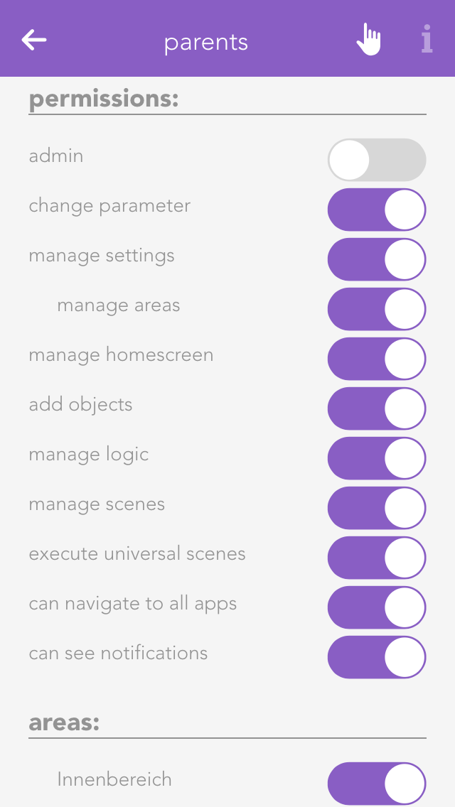
Admin
This level of rights gives the user full access to all possibilities in the system. All the following rights are deactivated, since they are all included in the admin rights.
Change parameter
Users in this group are allowed to change parameters, i.e. all settings accessible via the parameter symbol.
Manage settings
The user can open the settings (all apps – settings) and make changes. Exceptions are the user settings.
Manage home screen
The user can change the start page of the app, in other words, they can set favourites and move elements. See also “own home screen”.
Add object
The user can add new objects to the system, for example a new surveillance camera, a new Denon system, etc.
Edit logic
The user can create and edit logic elements.
Edit scenes
The user can create and edit scenes; otherwise scenes can only be executed.
Edit area
The user can create and edit areas.
Execute universal scene
The user can execute universal scenes such as close all blinds, switch on all lights, etc.
See all apps
The user can open all apps, otherwise they only have the possibility to open apps that are on the home screen.
See notifications
Notifications are displayed for the user (such as wind, alarm system, etc.).
Areas
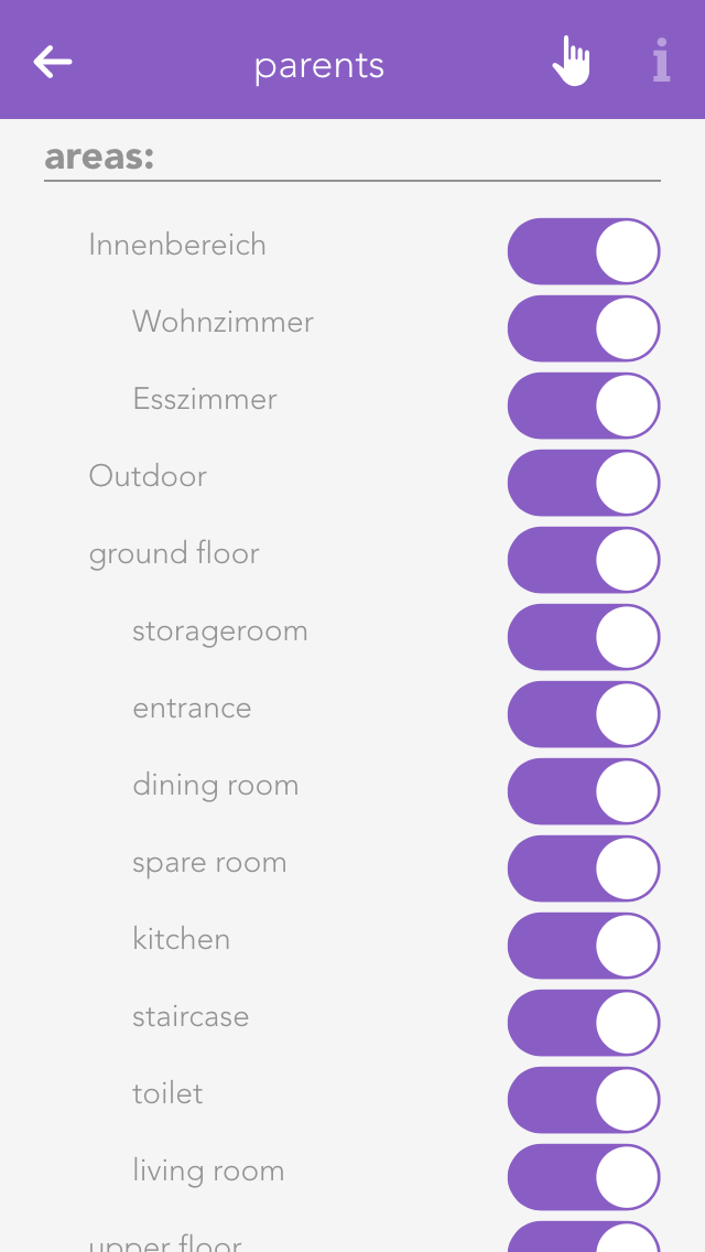
In “areas”, you can define which areas the users in the group will be able to access.
Light
A light in evonHOME corresponds to a lighting channel that is connected to an evonHOME light module. Once connected, each light can be switched on and off. In addition, you also have the pre-defined universal functions “all lights on” and “all lights off”.
You can find the lights under “all apps”.
Usage
You can switch a light on or off via the “power symbol” on the left side. The right-hand side of the panel shows you whether the light is currently switched on or off. Clicking on the element takes you into the extended operation or configuration of this light. You can switch the light on or off by clicking on the bulb symbol.
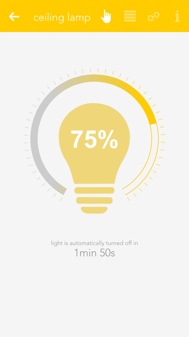
If you have a dimmable light, you can switch in on or off via the object panel. Of course, you can also control this dimmable light via the operator panel by setting the circular slider around the light to the desired value.
Configuration
Once a light has been given a name, you can configure it to suit your needs.
General
Mode
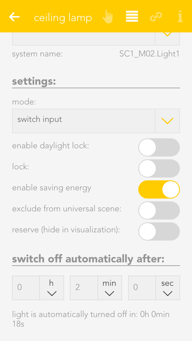
This setting determines whether this light is controlled by a switch or a presence detector. If you select “presence detector”, the settings to adjust the time the light is switched on are displayed.
Activate daylight lock
This option lets you prevent the light from switching on during the day (if there is sufficient light). This can be used for a hallway where the light is controlled by a presence detector.
Lock
If you activate “lock”, then the light cannot be switched on or off by the switch, nor by the presence detector.
Activate energy saving mode
This option lets you configure the light to switch itself off after a certain time. If you have activated this option, then the software shows you the settings for the time the light is to remain switched on. You can change this time to anything you want.
Remove from universal scene
An example of a universal scene is “all lights off”, where all lights are switched off. However, if you want a particular light to be excepted from this, then activate this option (useful for lighting an aquarium).
Reserve
If you have a module with spare connections, i.e. where no light is connected, the app still shows that the light is on or off, because the output is active (although no light is actually connected). The “reserve” field lets you hide lights that are not used/connected. You can reactivate this light via the corresponding module in the app “hardware”.
Dimmer
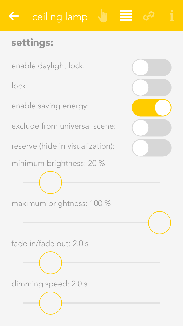
Minimum and maximum brightness
Minimum and maximum brightness: many lights only have a noticeable change in brightness within a certain range. Hence you can set a minimum and maximum brightness level so that the button can adjust brightness only between the minimum and maximum brightness levels.
Fade in time
This is the time that the light is to take to reach the desired brightness from being switched off.
Dim speed
This is how fast the brightness is reached when the button is pressed continuously.
Linking
Linking allows you to connect your light to other elements in your evonHOME.
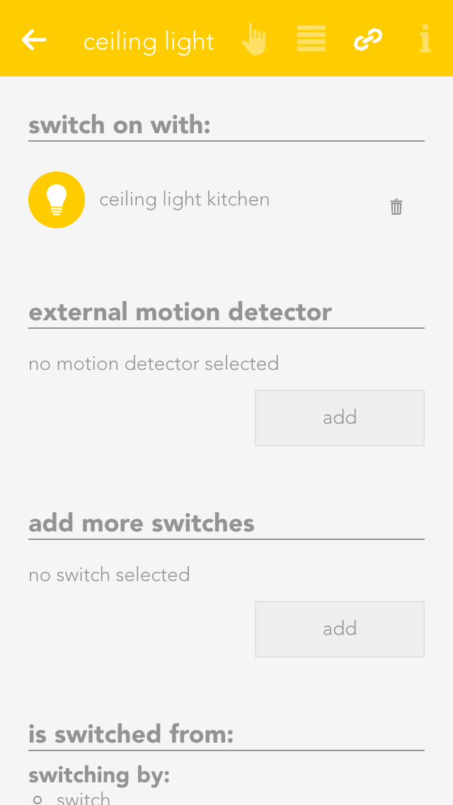
Switch on with
If you want this light to be switched on as soon as another is switched on, then use the function “switch on with”. The button “select” lets you select the other light you wish to link to this one.
Bewegungsmelder/Taster hinzufügen
Further presence detectors or buttons can be defined in one light channel to control the light.
The function of the linked button or presence detector depends on the autonomous light function, i.e. whether the button or presence detector mode has been selected.
Motion Detector
If a light channel is connected to the input of a presence detector, then this light will always be automatically switched off after the defined time independently of whether an additional button or presence detector is switched on.
A presence detector light can be immediately manually switched off using an additional button.
If the time for the presence detector is to be used, then the time for the light must be set to 0. If the time for the light is to used, then the time for the presence detector must be set to 0.
Additional buttons
The light can be switched off at any time with an additional button linked to this light channel (or on, if required). If the light is switched on via the button, it is also switched off after the defined period of time.
Note that in this case, the energy saving time cannot be 0, because otherwise the button input would be immediately switched off – and hence not seem to work.
Additional presence detector
An additional presence detector can also switch the light off after the defined period of time.
Note that in this case, if the energy saving time is defined with 0, then the on/off times for the light will vary due to the times defined by the presence detector.
Switch
If a light channel input is connected to a button, this light will be switched by every linked button or presence detector according to the autonomous function.
If no automatic switch-off time is defined (energy saving mode), then the presence detector can only switch the light on.
Additional button
The light can be switched on or off at any time using an additional button linked to this light channel.
Note that in this case, the energy saving time cannot be defined as 0, as otherwise the light would be switched off immediately after the button press – and therefore not seem to work.
Additional presence detector
An additional presence detector will always switch the light on and switch it off after the defined period of time.
Settings
You can configure settings that affect all lights in “all apps – settings – lights”.
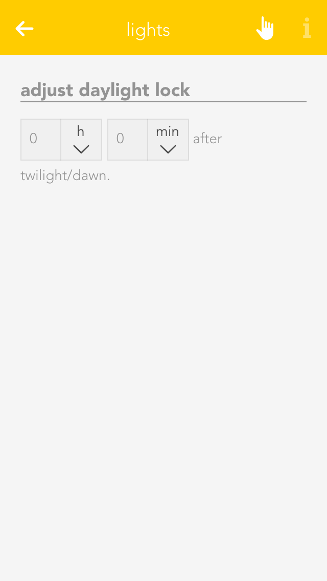
Daylight-lock-delayed switching
To configure the daylight lock, navigate to settings and select lights. You can adjust how many minutes after dusk you want the daylight lock to be deactivated and how many minutes after dawn you wish the daylight lock to be activated. In other words, if your evonHOME registers dusk at 8pm and you have set 10 minutes, then the daylight lock will be deactivated at 8:10pm.
Examples
You can find possible application examples here:
Blind
The app “Blinds” lets you operate and configure all shading elements in your system. You also have pre-defined functions such as “open all blinds” and “close all blinds”.
You can find Blinds under “all apps”.
Usage
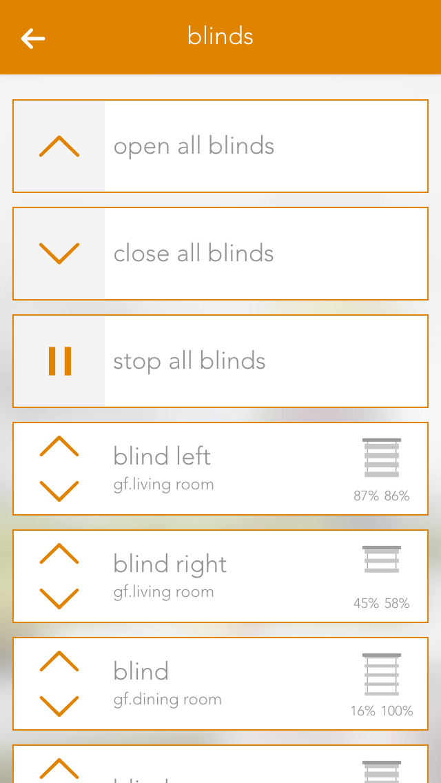
You can open or close your shading element using the arrows in the left-hand side of the object panel. The right-hand side of the panel shows the current position and the angle of the blinds.
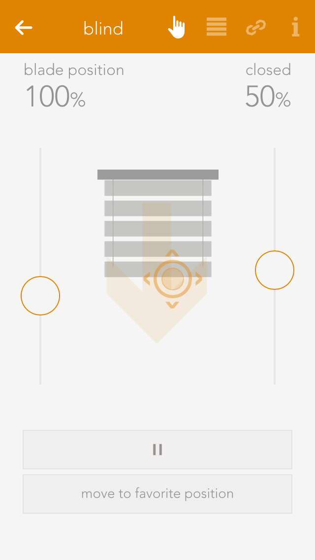
You can also operate each blind element via the operator panel by using the sliders on the right and on the left, or dragging the point in the middle of this window to the desired position. If you have defined a favourite position and wish to use it, simply click on the button “go to favourite position”.
Configuration
Apart from giving the shading elements individual names, you can customize them further to suit your needs.
Settings

Mode
This option is available when an 'evonHOME Blind 1344' (Schlotterer RETROLux) module is used. It allows to change the operation mode from 'standard blind' to 'without working position' or 'with working position'. In this case, 'working position' refers to a blind with a mechanical working position.
With working position
This mode is meant for use with the Schlotterer RETROLux venetian blind, which has a mechanical working position. It allows you to change the slat position with a short button press and to switch between 'closed' and 'working position'. In this mode, the slats can only be adjusted to a certain limit, which is caused by the underlying mechanical construction of these blinds.
Without working position
Choose this mode if you own a Schlotterer RETROLux venetian blind, which does not not have a working position. This mode grants you the ability to simulate a working position.
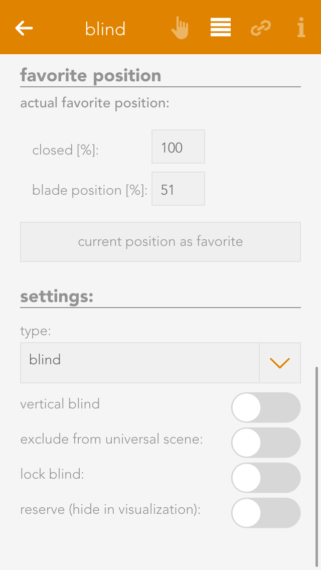
Type
Type lets you select whether the blind is a jalousie, a rolling shutter or a window (windows will be dealt with in an extra chapter). The jalousie has a position, an angle of the slats and a turnaround time, all of which must be considered in the calculation. A rolling shutter does not have an angle.
Vertical jalousie
If you have a jalousie that opens and closes vertically, then you can configure it here. If this is activated, you are then presented with a further option defining the direction you wish the jalousie to open.
Remove from universal scene
A universal scene could be “open all blinds”. However, if you want this shading element to be excepted from this universal scene, then activate this option.
Remove from wind-lock
If you do not want this blind to open in strong wind, then activate this option. If this option is not visible, then activate the wind-lock in the settings “all-apps – settings – shading”.
Lock blind
Use this option to lock a blind, which means that the shading position can no longer be changed via the app or the button.
Close at dusk
If you want the shade to close at dusk, then activate this option.
Reserve
If you have a module that has reserve connections, i.e. blinds are not connected to every output, then these elements are still displayed. The reserve function allows you to hide unused shading elements in the app. If you wish to see these unused elements, activate them in the corresponding module in the hardware section.

Extended parameter
If you use the 'evonHOME Blind 1344' module in combination with a Schlotterer venetian blind (and select the correct operation mode) additional options will be available to you here.
Those refer to the varied motion times, which are specific to Schlotterer blinds, like working position/snapping times. This settings are pre configured for optimal operation. In case you encounter any problems when switching between positions (working mode/closed) please contact your evonHOME partner, who can adjust those settings for you.
Travel Times
Travel time wizard
This wizard lets you easily and simply determine the travel times for your shading element. Simply follow the instructions and your travel times will be configured for you.
Use these travel times for all blinds
Pressing this button opens a dialog where you can have all blinds use these travel times. This is useful if all blinds are of the same type and you do not wish to have individual times for each blind.
Favorite Position

You can save your favourite blind position either by entering the values by hand or pressing the button “use current position as favourite”. The favourite position can be triggered via a scene.
Linking
Linking allows you to connect your shading elements to other elements in your evonHOME.

Connect with
If you want two shading elements to always have the same position and slat angle, then use this “connect with”. Navigate to “connect with” and press “select” to choose the shading element you wish to connect to.
Settings
Settings contains the configuration for general settings that are valid for all shading element. Navigate to “all apps – settings – blinds”.
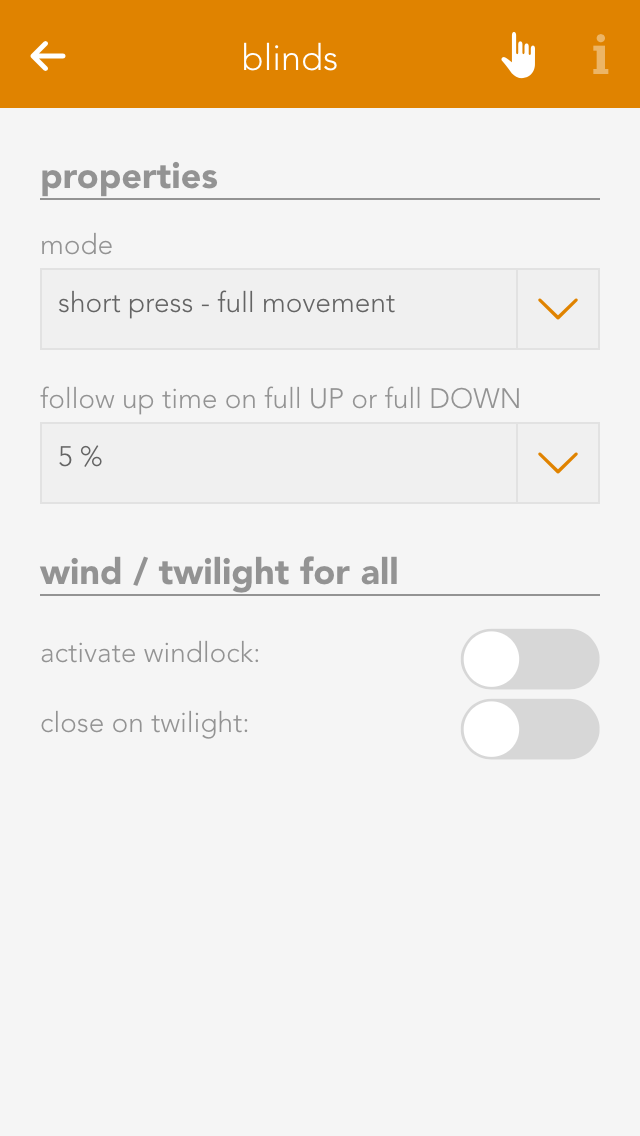
Mode
Short button press – completely up: If the blinds button is pressed for a short period of time, then the blinds will travel in the desired direction until either the blinds are fully open/closed, or a further press of the button causes them to stop where they are. A long button press sets the angle for the slats, i.e. after a wait time to correctly identify a long button press, the blind slats begin to turn until the button is released.
Short button press - set slats: A short button press changes the angle of the blinds and a long button press completely opens or closes the jalousie. A second button press interrupts the travel and the jalousie stops where it is.
Over-travel time
The over-travel time lets you define the percent of time to increase the time that the jalousie takes for completely UP to completely DOWN. This makes sure that the blinds are really open or closed.
Activate wind lock
If you have activated this option, then all shading elements are closed if it is windy. If you want to exempt elements from this wind lock, it can be done for each individual element.
Close at dusk
If “close at dusk” is selected, then all blinds will close as soon as dusk is detected. If you do not want all blinds to close at dusk, then deactivate “close at dusk” for each individual blind. In addition, you can also delay the closing at dusk by entering the number of minutes after dusk you wish to wait until the blinds close.
Indoor climate
The app “indoor climate” lets you operate and configure all room climate elements in your system. You also have the pre-defined central functions “all frost protection mode”, “all comfort mode” and “all energy saving mode”.
The app is located under “all apps” – “indoor climate”.
Usage
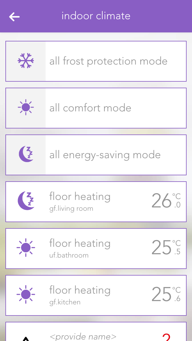
Clicking on the left-hand area of the object panel switches back and forth between comfort mode and energy saving mode.
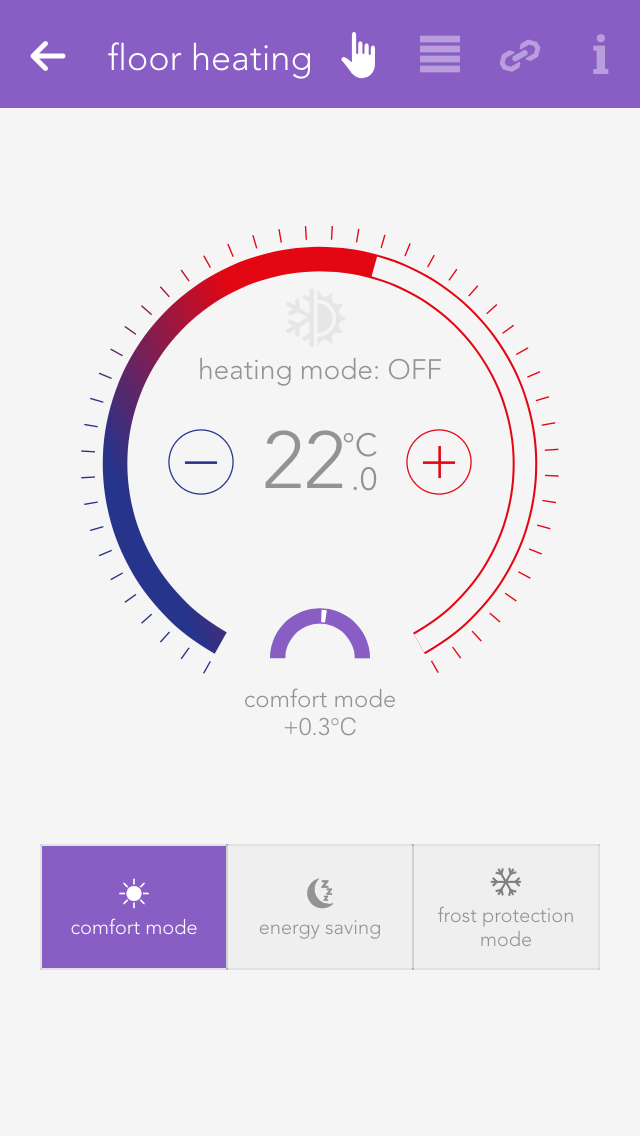
You can also select the operating mode using the three buttons located next to each other in the operator panel. The desired temperature can be adjusted in the circle above these buttons via the “+” and “-“ buttons, or you can simply click on the position in the circle that you want.
Configuration
General
Mode
If you have a module type C1114, you can only select FBR or FRB as actual value, i.e. you can only connect the module input with one room control panel. If the module is type C1244 you can select a PT1000 actual value or an external signal as an actual value, i.e. you can only connect one PT1000 to the module input and no control panel.
FBR
In FBR mode, all values are taken from the connected control panel. This includes the current room temperature, the operating mode, the temperature offset and the presence-based temperature increase. The mode can only be changed via the app if the auto-operating mode has been selected.
FBR only actual value
In FBR mode, the actual value is only taken from the room control panel. All other values are ignored.
PT1000 actual value
If you have connected a PT1000 to the module input, then you must select mode PT1000 actual value.
External actual value
All values from the room control panel are ignored in the mode “external actual value” and the actual value is provided by the evonHOME controller. A source for the actual value must be entered in the link panel.
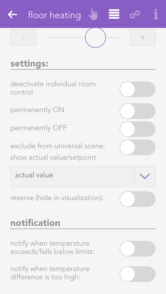
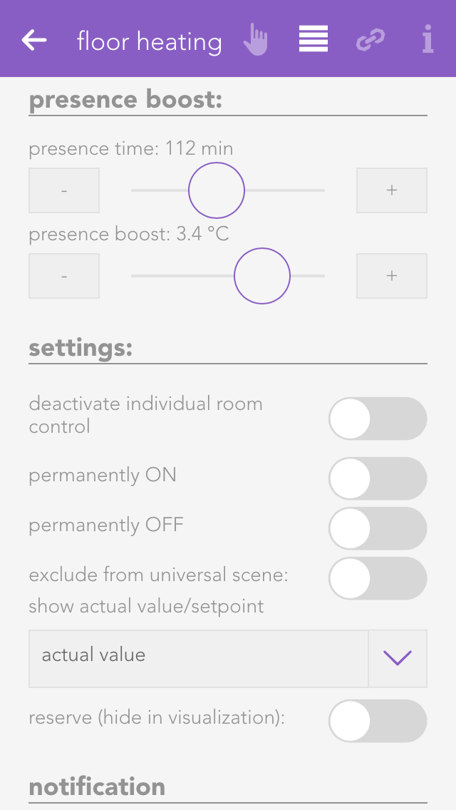
Permanent ON/OFF
The valve output can be permanently switched on or off, independently of the current temperature and the current operating mode.
Remove from universal scene
The valve output can be permanently switched on or off, independently of the current temperature and the current operating mode.
Display actual/desired value
This value determines whether the actual or desired value should be displayed in the object panel.
Reserve
Even if not all room climate channels are connected to a module, all four control elements are still displayed for this module. If you want to hide these unconnected control elements, then mark them as reserved. You can unhide them via the app “hardware” (all apps – “hardware”).
Setpoints
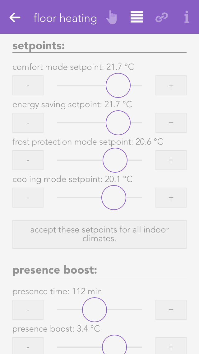
The desired values for the various operating modes are defined here. Clicking on the button “use this desired value for the entire room climate” opens up a dialogue with which the desired values in this room climate element can also be used for all other elements.
Presence Rise
If the presence button on the room control panel is pressed, the desired temperature of the room is increased by the defined value and time period.
Temperature Limit
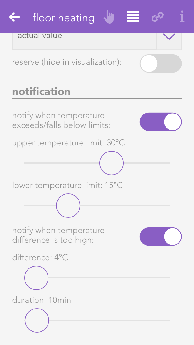
The item “temperature limit” lets you define a temperature limit, i.e. you can react with a scene if the value falls below or exceeds the limit. You can also activate notifications for falling below or exceeding the limit via “notifications for temperature limits”.
Linking
Links allow you to connect your room climate with other elements in your evonHOME.

Window contact
To ensure that heating is suspended when a window is open, you can add as many windows as you want via the button “add”. If one of these windows is opened, the heating will automatically enter into frost protection mode. As soon as the window is closed, comfort mode will be reactivated.
Settings
The settings for all room climate elements can be found under “all apps” –“settings” – “indoor climate”.
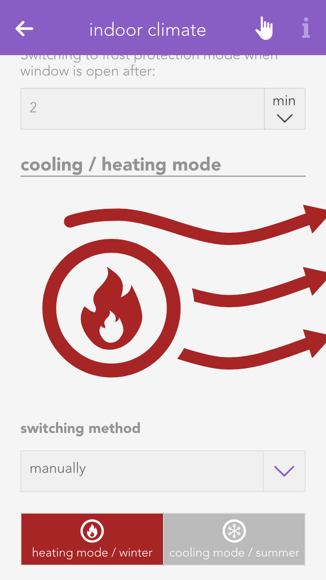
Can cool
If your heating system supports cooling, then you can activate this option. Warning! If your heating is not suitable for cooling, using this option could lead to malfunction. If in doubt, please contact a heating specialist.
In- and Outputs
A few inputs and outputs in evonHOME are used similarly in different modules. This is described in this section.
Switches
A switch can be connected to a light module, blind module or a digital module. A switch has a pre-defined function for a light or blind module. Every switch can be simulated in evonHOME for test purposes.
These switches can be found under “all apps” – “switches”.
Configuration

Naming
If you have connected your switch to a light or shading module, then the switch is automatically named according to the light or blind. If you wish to give it a different name, then deactivate the option “same name as blind/light” in the parameter panel and give the switch a new name. If you have connected your switch to a digital module, then you must name it yourself.
Reserve
If you have a switch in your system that you don’t use, then you can hide it by deactivating the option “reserve “hide in display” in the app “ switches”. To unhide it, you can find your switch in the app “hardware”.
Mode
If you want to change the mode, i.e. define the switch as a presence detector or a digital input, then you can do this in the parameter panel under “mode”. Not every module can change the mode however, or not all possibilities are available. This means that the light modules’ switch can only be converted to a presence detector. Switches for a blind element cannot be converted. Switches for digital modules have all three modes.
Simulation
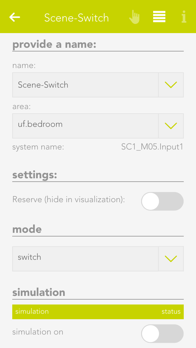
If you have linked a switch to a scene and would now like to simulate this scene, then there is no need to go to the switch and press it every time, you can use simulation to create the switch press. Simply activate the option “simulation” in the operator panel to see 3 buttons that you can use to simulate switch presses.
Warning: If you leave the simulation mode activated, the autonomous functions will not work!
Scene
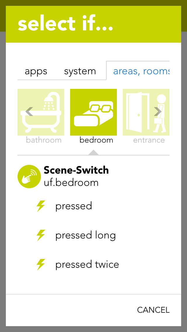
You can use the switches for a scene (assuming it as been named). In the scene “if …” just select the switch and decide if you want the scene to be executed after a single, double or long press.
Settings
Open the switches settings (“all apps” – “settings” – “switches”) if you want to define the times for a press and double-press. Select the desired values and confirm them by clicking the button “use values for all switches”.
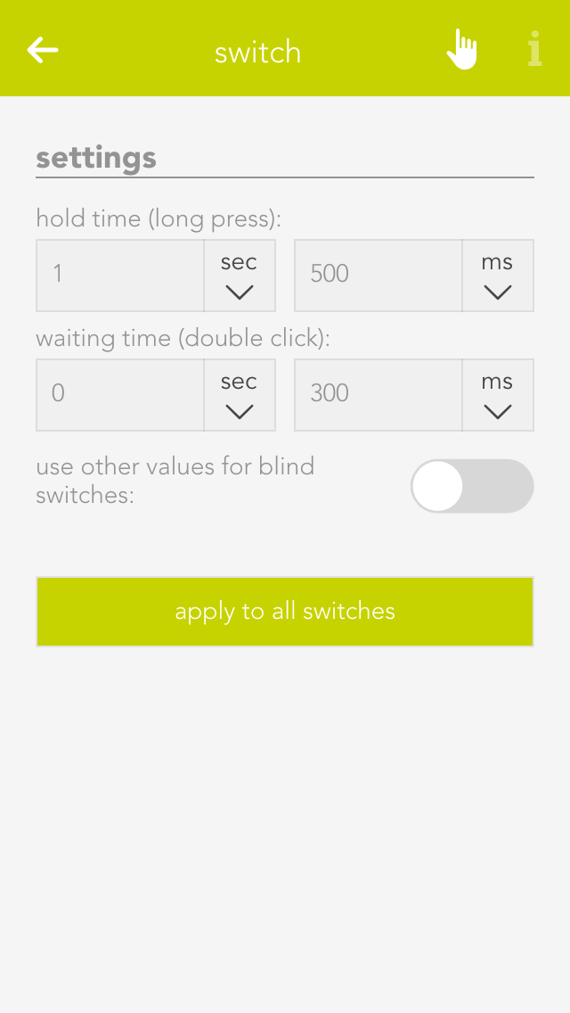
Hold time (long button press)
A switch must be pressed for at least thus time to be recognized as a long button press.
Wait time (double-press)
The gap between two switch presses must be as least as big as the defined wait time to be recognized as a double-press.
If you wish to define different values for a switch that is connected to a blind module, then activate the option “use other values for blinds”.
Motion Detector
A motion detector can be connected to a light module or a digital module. The motion detector has a pre-defined function when connected to a light module. Motion detectors can be simulated in evonHOME for test purposes.
You can find motion detectors under “all apps” –“motion detectors”.
Configuration

Naming
If you have connected a motion detector to a light module, then it is automatically assigned the same name as the light. If you wish to assign a different name, then deactivate the option “same name as light” in the parameter panel and enter the name you wish. If the motion detector is connected to a digital module, then you must assign it a name yourself.
Invert
If the motion detector is connected to a digital module, you have the possibility to invert the logic by activating the option “invert” in the operator panel.
Reserve
Should you have a motion detector in the system that you do not use, you can hide in from the app “motion detector” by activating the option “reserve (hide in display)” in the parameter panel. To unhide it, you will find your movement detector in the app “hardware”.
Mode
If you wish to change the mode, i.e. convert the motion detector input to a switch or a digital input, you can do this by changing the mode for the motion detector in the parameter panel. Not all modes can be changed in all modules, or not all possibilities are available. This means that a motion detector for a light module can only be changed into a button. All three modes are available for motion detectors for a digital module.
Simulation
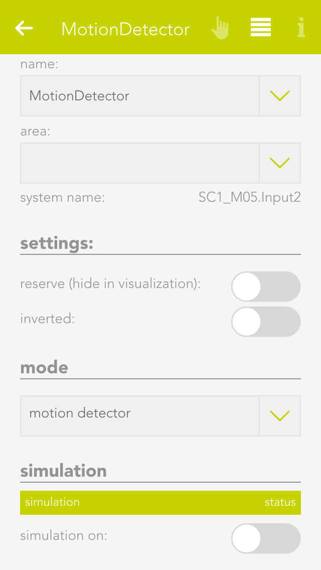
For example, if you have linked a motion detector to a scene and you would like to test this scene, then you do not have to go to the motion detector and activate it every time, you can change the state using simulation. Simply activate the option “simulation on” in the operator panel to see the option with which you can change the state.
Warning, if you leave the simulation switched on, the autonomous function will not work!
Scenes
You can also use the motion detector for a scene (in as far as it has been named). In the scene, select the motion detector for “if …” and decide if you want the scene to be carried out on the rising or falling edge of the signal.
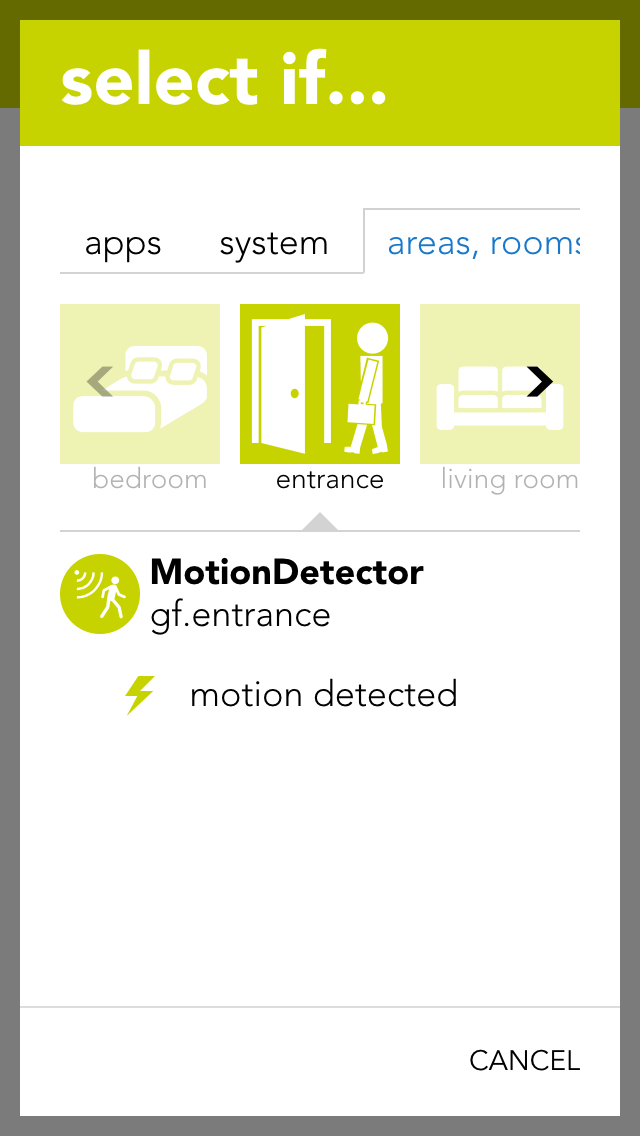
Rising edge
The electrical contact of the motion detector has been activated.
Falling edge
The electrical contact of the motion detector has been deactivated (after the internal time of the motion detector).
Digital Input
You can use a digital input for functions not provided by any evonHOME function module. You can name each digital input and simulate then for test purposes.
You can find the app “digital inputs” under “all apps” – “digital inputs”.
Configuration
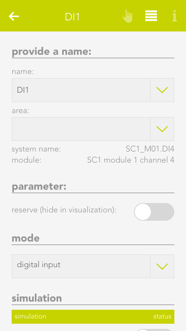
Reserve
If you have a digital input in your system that you are not using, you can activate the option “reserve (hide in visualization) to hide this digital input in the app “digital inputs”. (To unhide this, the digital input can be found in the hardware app)
Mode
If you wish to change the mode, i.e. convert a digital input into a button or a movement detector, this can be done in the parameter panel for the digital input under “mode”.
Simulation
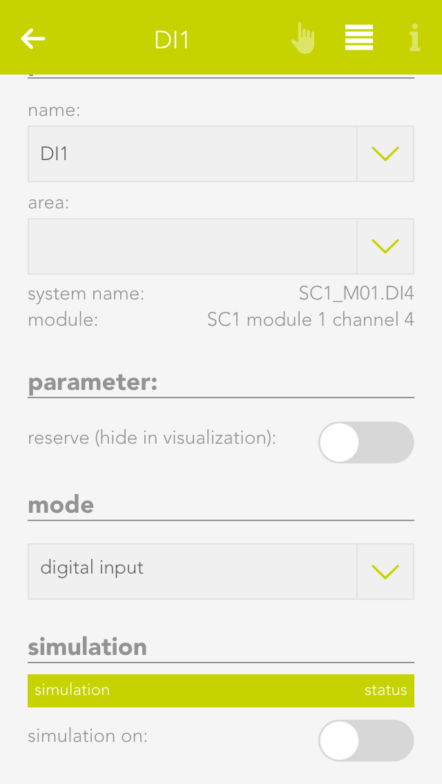
If you have connected a digital input to a scene and would like to test the scene, you do not have to navigate to the digital input and activate it every time, you can change it directly via simulation. To do this, activate “simulation on” in the operator panel to see the option “simulation value” with which you can change the state. Warning, once the simulation has been activated, the autonomous function will no longer work! Any changes in the state of the input “hardware” will be overwritten by the simulation.
Scenes
You can also use a digital input for a scene (in as far as it has been named). Select the digital input in the scene’s “IF ….” and decide whether you want the scene to be carried out on the rising or falling edge.
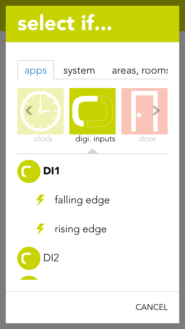
Rising edge
The electrical contact of the digital input has been closed.
Falling edge
The electrical contact of the digital input has been opened.
Digital Output
The app “digital outputs” provides you with an overview of all digital outputs in your system. This is where you can name them and change the state of the outputs.
The app “digital outputs” is located under “all apps” – “digital outputs”.
You have two possibilities to change the state of a digital output. Either you can click on the power symbol on the left in the object panel or you can click on the button “switch” in the operator panel.
Configuration
You can give a name to a digital output in the parameter panel and optionally allocate it to a room.
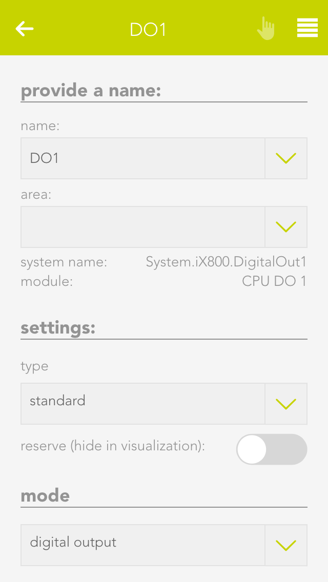
Save output if bus fault
If the output is active when the bus connection to the CPU fails (for example if the 24V power supply to the module fails), this option lets you guarantee that the active remains activated even in a fail state. If this option is not activated, then the output is reset after every bus connection failure.
In safety-critical controllers, it should be carefully examined whether this function should be activated, since this output is kept active if the system fails.
Mode
With the mode setting, you can change the behavior of the output once it is active. The following options exist:
-
Standard
This ist the normal setting for a digital output. With this, the output stays active until the signal ends. -
Minimum on duration
With this mode, the output stays active for at least the specified time, even when it is deactivated before. -
Pulse
In this mode, the output will automatically be deactivated after the defined timeframe.
Reserve (hide in visualization)
If you have a digital output in your system that you do not use, then you can hide this digital output in the digital output app by activating the option “reserve (hide in visualization)” (located in the parameter panel). (To unhide, the digital output can be found in the hardware app).
Change mode
If you wish to change the mode, i.e. convert a digital output to a socket, then you can do this by changing the mode for the digital output in the parameter panel.
Scenes
You can also use a digital output for a scene (in as far as it has been named). In the scene’s “if …” simply select the digital output to see the following possibilities:
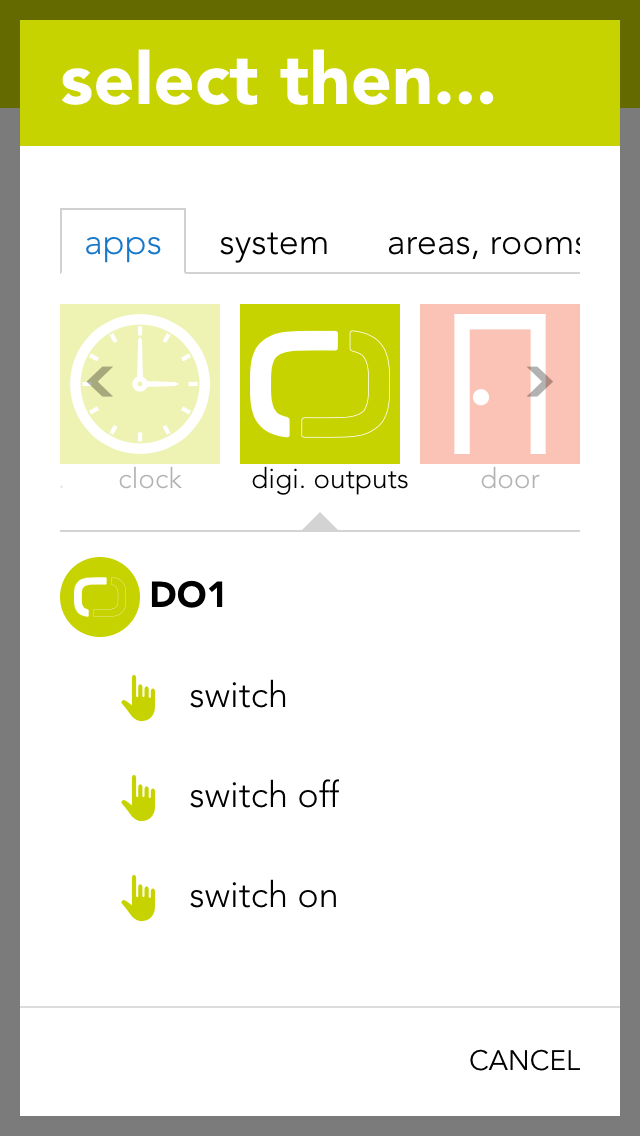
Switch off
The digital output is switched off.
Switch on
The digital output is switched on.
switch on for
The digital output will be switched on for a defined amount of time.
Toggle
The state of the digital output is toggled.
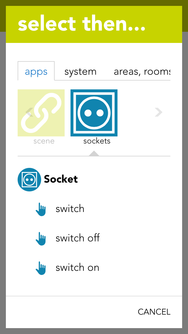
Socket
The app “sockets” provides an overview of all sockets in your system and allows you to name them and change their state.
The app “sockets” can be found under “all apps” – “sockets”.
You have two possibilities to change the state of a socket. Either you can click on the power symbol on the left in the object panel or you can click on the button “toggle” in the operator panel.
Configuration
The parameter panel lets you give the socket a name and optionally allocate it to a room.
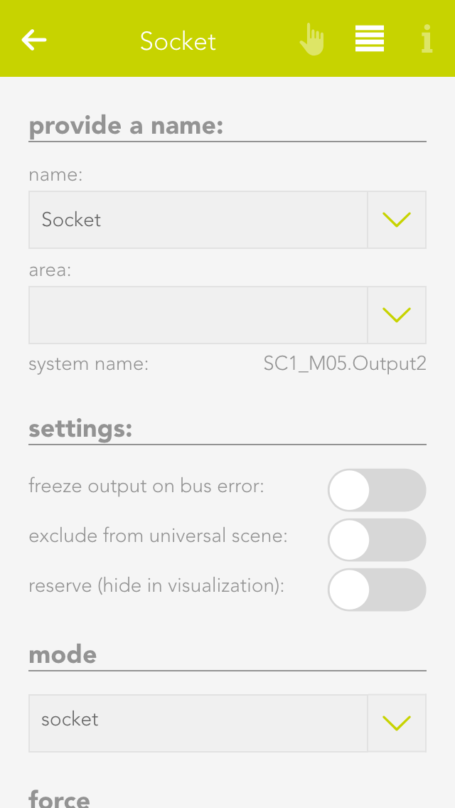
Save output if bus fault
If the socket is currently active and the bus connection to the CPU fails (e.g. the 24V power supply to the module fails), then activating this option will guarantee that the socket remains active even in a fail state. If this option is not activated, then the socket is reset after every bus connection failure.
In safety-critical controllers, it should be carefully examined whether this function should be activated, since this output is kept active if the system fails.
Reserve (hide in visualization)
If you have a socket in your system that you do not user, you can hide this socket in the app “sockets” by activating the option “reserve (hide in visualization) (located in the parameter panel). (To unhide, the socket can be found in the app “hardware”).
Change mode
If you want to change the mode, i.e. convert socket to a digital output, then this can be done by changing the mode in the socket’s parameter panel.
Scenes
The socket can be used for a scene (in as far as it has been named). In the scene’s “if….”, select the socket and one of the following possibilities:
Switch off
The socket is switched off.
Switch on
The socket is switched on.
Switch on for
The socket is switched on for the time you define.
Toggle
The status of the socket is toggled.
Analog Input
An analog input can measure voltage in the range 0-10V. This voltage is then scaled to the range defined by the user. This value can be used by the user for calculations (using logic), or simply to trigger scenes if the value exceeds or falls below certain (definable) limits.
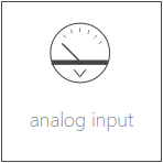
The analog inputs are located under “all apps” – “analog inputs”.
Configuration

Minimum/Maximum
Minimum and maximum limits of the measured value. These inputs must be taken from the description of the sensor used. For example, you wish to measure the humidity in a room and use a sensor with a 0-10V output signal. The sensor documentation tells you that the sensor can measure humidity from 0% to 100%. The minimum limit is hence 0 and the maximum limit is 100.
Number of decimal places
Indicates the number of decimal places used to calculate the value.
Dimension
This is where you define exactly what you wish to measure with this analog input (e.g. temperature °C).
Notification on limit violation
If the value of the analog input falls below the lower limit or exceeds the upper limit, then you will be notified by the system if this checkbox is activated.
Upper limit
Enter the upper limit here. If the value exceed this limit, you can react with a scene by selecting the trigger for “value above upper limit” in the “IF …” statement.
Lower limit
Enter the lower limit here. If the value falls below this limit, you can react with a scene by selecting the trigger for “value below upper limit” in the “IF …” statement.
Data Description
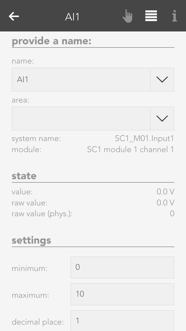
Raw value
A raw value is the voltage (0-10V) measured on the input of the module.
Raw value (phys.)
Corresponds to the output of an analog/digital converter and is used for the calculation into the physical measured value.
Value
Corresponds to the scaled value resulting from the raw value, minimum and maximum.
Value = (Raw value phys. / Raw value phys. MAX) * (Maximum – Minimum) + Minimum.
Simulation
If you wish to simulate the value for an analog input, this is easily done by activating the option “simulation on” in the operator panel and selecting the desired value in the slider. This can be useful if you have defined a scene you wish to be carried out if a limit is exceed and you wish to test what happens.
Analog Output
An analog output outputs voltages in the range 0-10V. To do this, enter a value in your defined area and this will be output as a voltage between 0-10V.

The analog outputs can be found under “all apps” –“analog output”.
Configuration
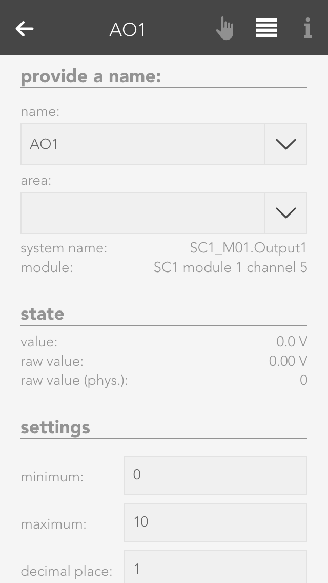
Minimum/Maximum
The calculated value is in the range between the minimum and maximum. This means that if 10V are meant to be present on the module output, then the value must be set to the defined maximum value (100%).
Number of decimal places
Defines the number of decimal places for the calculation.
Dimension
Define here what you wish to control with this analog output (e.g. speed: %)
Stored value upon bus error
If the control were to fail, the last value would be stored if you have activated this option. If you did not activate this option, the value present when the control failed will be lost.
Data Description
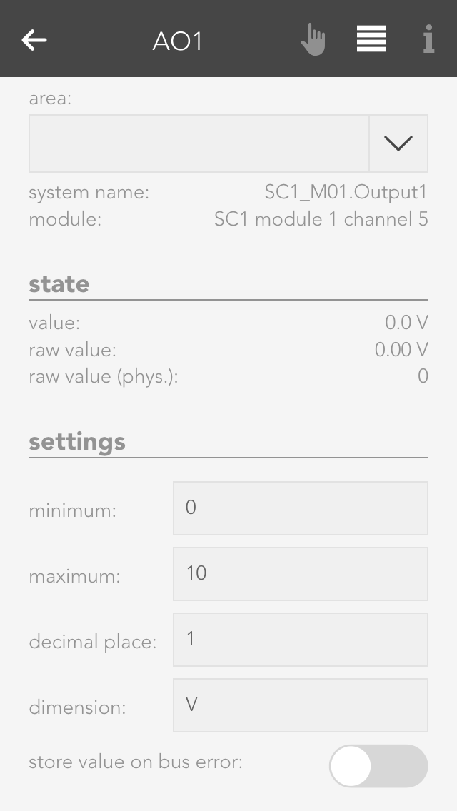
Raw value
The raw value is the voltage 0-10 V that is present (set) on the output of the module.
Raw value (phys.)
This is the digital value sent to the module.
Value
This is the scaled value that has been converted to the defined range between minimum and maximum, with the defined number of decimal places and the defined dimension.
Setting Values
There are two different possibilities to set a value to the analog output. Either you set the value via the operator panel for the analog output, or you select the analog output in a scene for the “if …” statement and then select “write value”. Then you can change the value by clicking on the pencil.
Temperature Sensor
You can view all the module channels to which you can connect temperature sensors (e.g. PT1000) in the app “temperature”.
The temperature sensors can be found under “all apps” – “temperature”.
Configuration

With module A1240, you can only set the temperature limits (as described in the item “scene” above). This module can only accept temperature sensors of type PT1000.
If you posses a module of type A1380, you can connect temperature sensors of type PT1000, KTY81-110 and KTY81-210. To ensure that the modules know which sensor has been connected, you must navigate to the parameter panel for this temperature sensor and select the type under “mode”.
Simulation
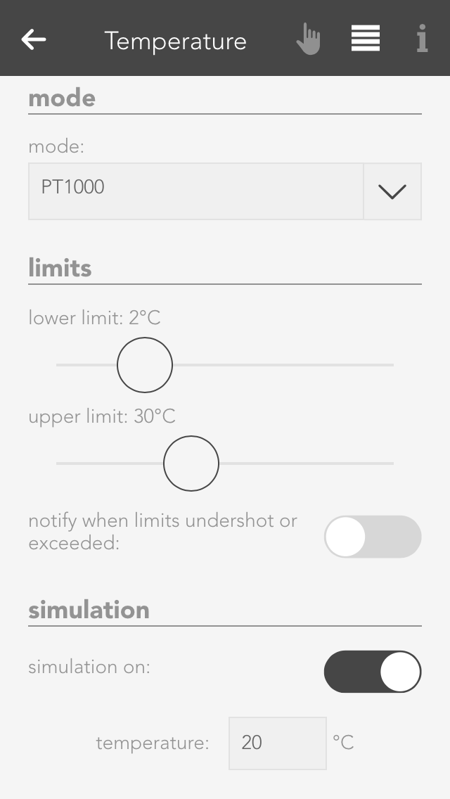
If you want to know what happens if the temperature rises above or falls below a certain value, then you don’t need to cool or heat the temperature sensor. You can use the option “simulation” in the operator panel. Simply activate the checkbox “simulation on” and enter the desired temperature in the input field that appears. Warning, do not forget to deactivate the simulation when you have finished testing.
Usage
Hier werden Dir einige Beispiele beschrieben wie Du einen Temperatursensor verwenden kannst.

Outside temperature
If you want a temperature sensor in your system to determine the outside temperature, you need to add it using the button “add” in the global settings under the item “outside temperature” and drag it to the first position. (More information in this in the documentation for global settings).
External current value for room climate zone
If you want to use this temperature sensor as an actual value for a room climate zone, then you must set the mode to “external actual value” in the desired room climate zone under “settings” and then connect the temperature sensor with it (more detail in the chapter “room climate”).
Scene
In order to link a temperature sensor with a scene, you must first allocate a name to it. Then you can set an upper and a lower temperature limit in the parameter panel that you can use in the scene for the “if …” statement. You can create a scene for the temperature falling below the lower limit or rising above the upper limit.
Logic
If you are an expert with the app “logic”, you can also use this temperature sensor here by connecting the input of a logic element with the current temperature reading.
Settings
The general settings for your evonHOME can be found under “all apps” – “settings”.
External access

This is where you determine whether you have Internet access to your evonHOME. If external access is active, then you can access your evonHOME using your evonHOME ID from anywhere.
Global Settings
Global settings let you define what is responsible in your evonHOME for activating wind, rain, frost, dusk states. For example, if you have connected a rain sensor, this is where you would find the settings for your system to display whether it is raining or not. The global settings can be found under “all apps” – “settings”.
Rain

You can connect the rain sensor to the appropriate input of the iX800 controller. IF you also have a weather station or Internet weather, then you need to select which element invokes “rain” in the system. Simply drag the box with the text “iX800” in the item rain to the first place (if more than one box is available) to be able to use the controller’s rain sensor input.
If you have connected your rain sensor to a digital input, then you can select it using the button “add” and drag it to the first position.
Twilight

The dusk sensor can be connected to the dusk input on the iX800 controller. If you also have a weather station or Internet weather, then you need to select which element invokes “dawn/dusk” in the system. Simply drag the box with the text “iX800” in the item dusk to the first position (if more than one box is available) to use the dusk input on the controller.
If you have connected your dusk sensor to a digital input, then you can select it via the button “add” and drag it to the first position.
Wind Alarm

Connect your wind contact to the wind input on the iX800 controller. If you also have a weather station or Internet weather, then select which element invokes “wind alarm” in your system. Drag the box with the text “iX800” in the item wind to the first position (if more than one box is available) to use the wind contact on the controller.
If you have connected your wind contact to a digital input, then select it using the button “add” and drag it to the first position.
Outdoor Temperature

You can select the value you wish to use for the outside temperature by dragging the element to the first position in the item outside temperature.
If you wish to measure the outside temperature using a sensor, you can do this by clicking the button “add”.
In addition, you can define a value for the frost and heat warning (in the parameter panel). As soon as the outside temperature rises above or below this value, a scene or a notification will be invoked.
Geo Coordinates

The sunrise and sunset times can be calculated using the geo-coordinates. These times are then used for the dawn/dusk calculations. To make sure that the dawn/dusk calculation is performed using the geo-coordinates, drag it to the first position in the item dawn/dusk.
The geo-coordinates can be entered using the decimal point format. To find out which geo-coordinates your house has, simply go to www.maps.google.at and search for your house. Right-mouse click on your location and select “what is here?” to display your geo-coordinates (the first value is north and the second east).
If you wish to change the calculated times then activate the option “adjust time for dawn/dusk”. This will let you adjust how many minutes earlier or later you wish dawn and dusk to be.
Simulation
If you wish to simulate what happens if it rains, for example, then you can simply simulate the occurrence of rain by activating the option “simulate rain” in the item “rain” and then activate the option “rain on”. This is also true for wind, outside temperature and daylight. Warning, do not forget to end the simulation when you no longer need it (e.g. deactivate “rain simulation”).
Notification

You can define which events for you would like to receive notification of in the parameter panel.
Updates
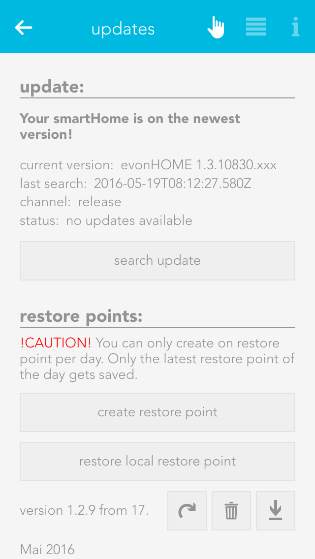
The updates screen lets you make sure your evonHOME is up-to-date. Simply click the button “search for updates” and if an update is available, click “execute update”. If you wish your system to automatically search for updates, activate the setting “search for updates automatically” in the operator panel. You can also see the current version and the time of the last update and the update channel here.
Furthermore, you can create recovery points, which allow you to reset your evonHOME to an earlier state if you have inadvertently maladjusted parameters. Such recovery points are recommended once you have named all your lights, blinds, etc. and have set them up as you require. Use the button “reset to factory setting” to reset your evonHOME to the original factory settings.
Saved recovery points will be shown in a list, where you can delete, recover, or download them at any time.
You can create one recovery point per day. If you create more, only the last one will be saved. In addition, you can also restore your system with a downloaded recovery file by using the button 'restore local restore point'.
A recovery point of your current configuration is created automatically before every update.
System Settings

Project name
You can give your evonHOME any name you like in the system settings.
Controller new start
This function restarts your system. Note that while the system is restarting, you do not have a connection to the CPU.
Manifest
This item shows you whether your visualization is up-to-date. The setting “automatic reload” lets you update your visualization automatically if it is not up-to-date.
System Diagnose
All information pertaining to your system can be found under the item system diagnostics, such as current version, memory used, IP address, etc.

You can also look at cycle times. This is an indication of the load on your evonHOME system. You can also see the last five peak values. The cycle time is the time required for a complete run of the program.
Time
“Time” lets you see the current time and date used in your controller (server time), the time zone your controller is in and the time of the device you have used to connect to your evonHOME (mobile phone, tablet …).
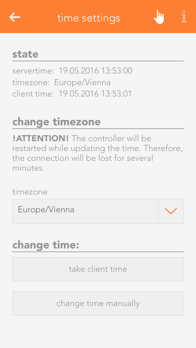
The time zone lets you allocate the desired time zone to your controller. The item “set time” allows you to set the time in the controller. The button “use client time” allocates the time used by your device (mobile phone, tablet) to the controller. The button “set time manually” lets you set the time and the date for your controller yourself.
Network
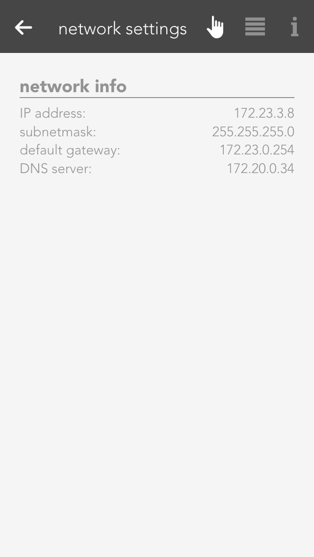
This area contains all network settings for the network used by your evonHOME. You can also configure whether the IP address and DNS server should be automatically allocated, or whether you wish to define them yourself.
This app lets you send email notifications via an existing email account. The “test mail” function is used to test the configured settings. You will need to obtain the required settings for the SMTP server from your email provider.

You can either send a test email or you can select “send email” in the “system” tab in a scene “if …” statement. Then all you need to do is enter the sender, recipient, subject and text.
If you wish to register with your Gmail account, then you must allow “less secure apps” in your Gmail account. Simply open the link to the Google Config and click “activate”.
Dictionary
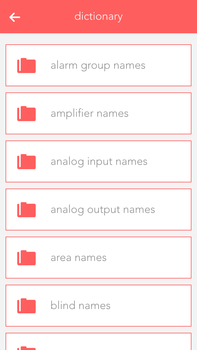
You can edit the pre-defined names in the dictionary. These names will be suggested to you when you wish to name a light, a blind, etc. However, you can even select a different name when naming your elements. The names in the dictionary are only a guide.
Devices
The “devices” app shows you all mobile devices that have been registered in your system.

The “devices” app is under “all apps” – “settings” – “devices”.
Information

If you open a device, the display shows you the name and model of the device in the operator panel. The parameter panel shows detailed information concerning the device.
Configuration

If you wish to receive notifications on this device (e.g. window is open), then you need to activate the checkbox “receive push notifications”.
Hardware
The hardware app lists all modules that are connected to your system. If you wish to obtain a list of module channels, then all elements in this module are clearly displayed and in the correct order, the way they are connected to the module. This view can make it much simpler for you to name the individual elements, since you immediately know which module and which channel you wish to name.
The hardware app is located under “all apps” – “hardware”.
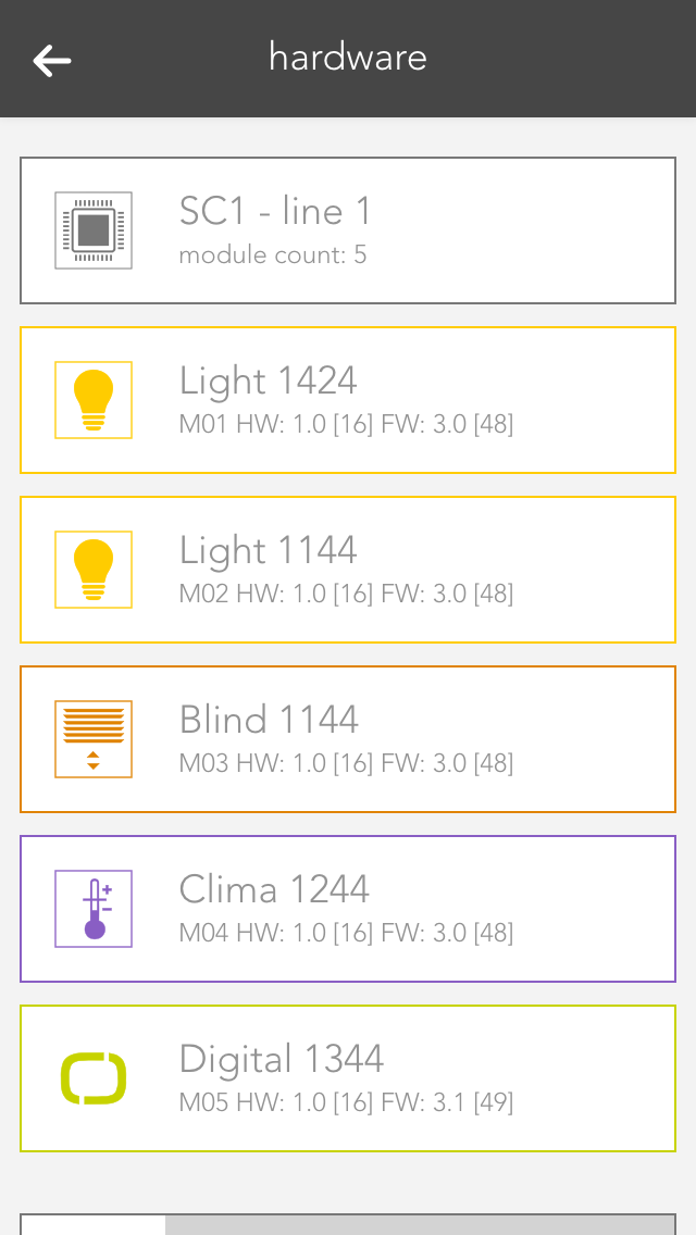
Hierarchically above the modules, you can see which line the module is located in (e.g. SC1 – line 1).
Line

If you open the line, the first thing you will see at the top is general information about the line. The item “cycle time” lets you define the cycle time for your bus line (standard is 200 ms). “Required cycle time” shows the time that is required for the operations. “Total cycle time” is the time required by the bus for a cycle. “Peak” is the peak value of the cycle time. This can be reset using the button “reset peak”.
Modules

By opening a module (click on the right-hand area), you will see all necessary information pertaining to this module. The button “display channels” displays the available channels in this module. The button “reset” resets a module, meaning that this module is reset to factors settings.
Module Channels

Click on the left-hand are of the object panel or on the button “displays channels) in the operator panel to see a list of module channels. Taking a light module as an example, you will be able to see the four channels with their corresponding button/movement detector and a light. This is the exact order that the button/movement detector and light are connected to the module, i.e. channel 1 is the light that is connected on the far left of the module.
Scenes
Scenes are an easy-to-use and yet powerful tool to personalize your evonHOME and adapt the controller to your requirements. Without programming – directly from the app!
Scenes can help you to customize your evonHOME without a single line of code. This is done using the IF THEN principle, i.e. IF a button is pressed, THEN open all the blinds in the room. This principle allows you to combine almost all functions in your controller with each other and to form relationships between them. Creating scenes is not complicated. And if scenes are not sufficient, you can extend your evonHOME with logic.
You can find scenes under “all apps” – “scenes”.
Creating Scenes
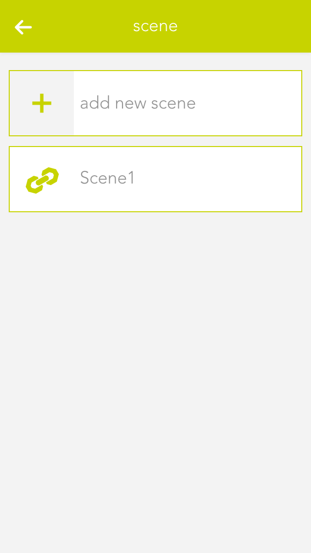
To create a scene, simply open the app “scenes” and select “create new scene”. Then open the operator panel for this scene. Enter the name and optionally a room. Then you can start with the configuration (described below).
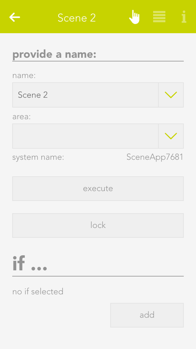
If you want to invoke a scene from the visualization, you can do this via the left-hand area of the object panel or via the operator panel with the button “invoke”. Otherwise the scene is invoked automatically if the condition you selected using the “IF” statement is true.
If
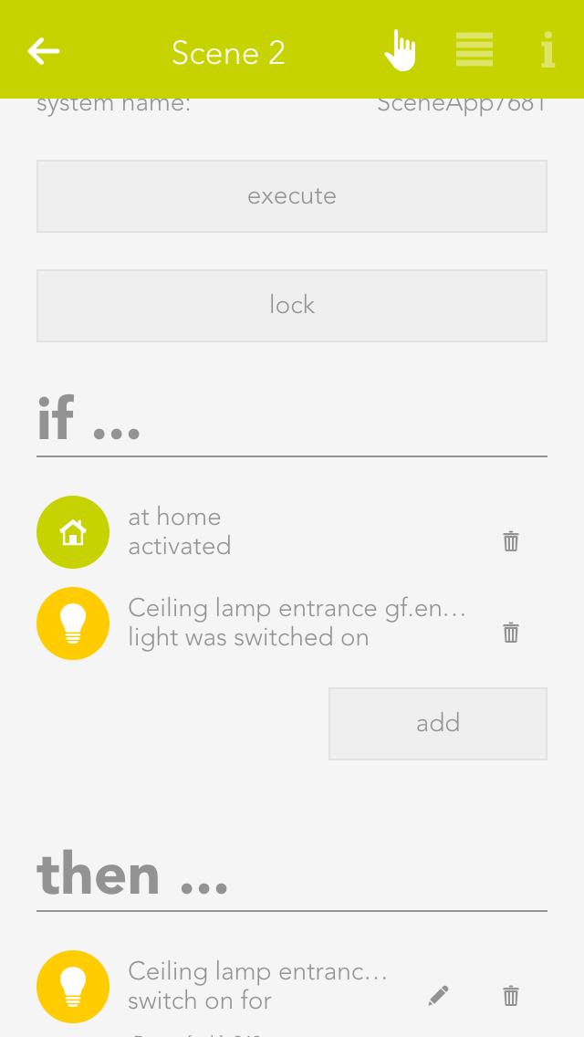
To add a trigger condition, click in the area “IF” on the button “add” and a window will open where you can add a trigger condition.
For example, if you add a button then you have three options:
- Pressed
- More press
- Double press
If you want to invoke a scene only via the app, you do not need a trigger condition.
If you wish to add several “IFs”, the scene can be invoked by each individual trigger condition, independently of each other.
Then
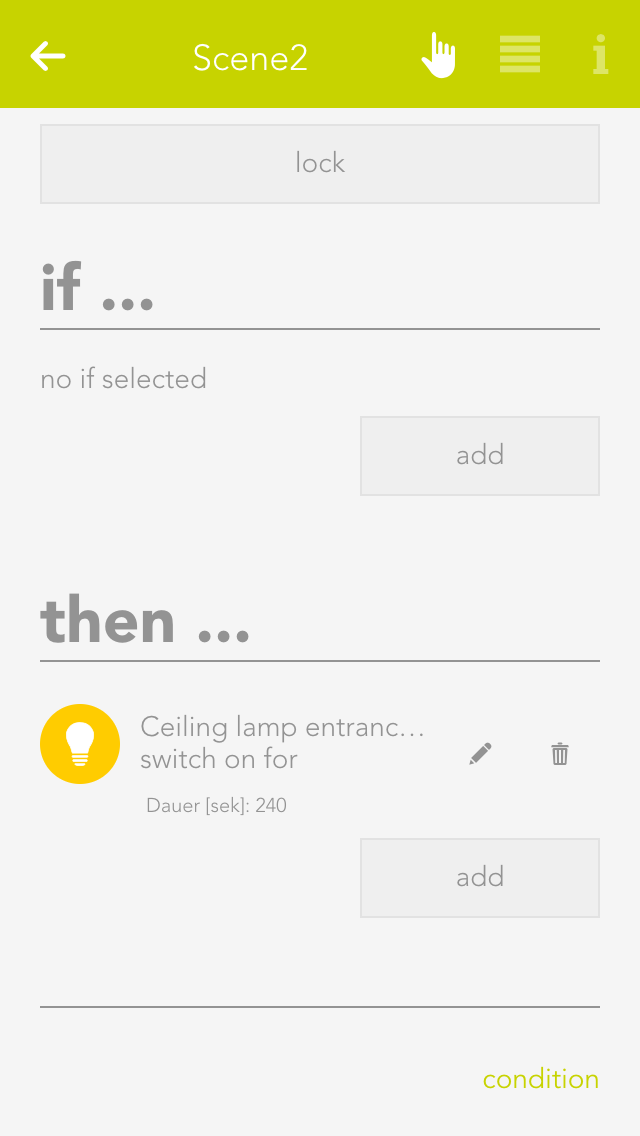
Click on the button “add” in the area “THEN” to select the action you wish to be invoked from the window that opens. For example, you have the possibility to switch lights on or off, to close shading elements or to move them to a specific position, etc.
For example, if you wish to move the blinds to a specific position, then you are offered the opportunity to define the exact position of this blind and the angle of the slats.
Conditions
If you only want a scene to be invoked under certain conditions (for example only if it is raining), then you can do this using conditions.
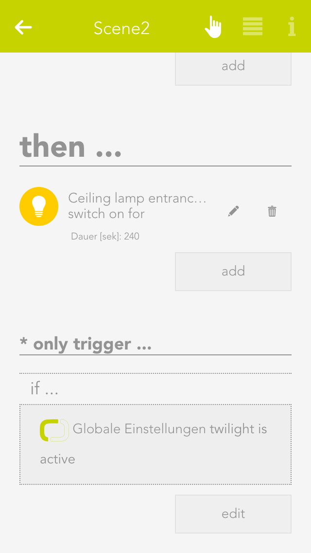
To do this, click at the bottom of the overview on “conditions”. Select here the “only invoke if” and then you can select the corresponding value (e.g. under system – house status the value “rain active”.
After adding this value, you can select others. These are combined using AND or OR logic. If several values are combined via an AND, then all must be active (e.g. “rain active” AND “wind active”) for the scene to be invoked. IF several values are combined via an OR, then at least one of these values must be active (e.g. “rain active” OR “wind active” OR “both active”).
You can edit a condition by clicking on the pencil symbol and delete it by clicking on the trash can symbol.
If a scene is locked due to condition, you can see a padlock in the left-hand area of the object panel, which is also displayed in the operator panel.
Examples
Garden Watering
The following example shows you how to irrigate your garden using a weekly programme and scenes.
You own a garden irrigation system and would like to activate it at defined times. The garden irrigation system is connected to a digital output, i.e. if this output is active, the irrigation system is switched on. If the output is inactive, the irrigation system is switched off.
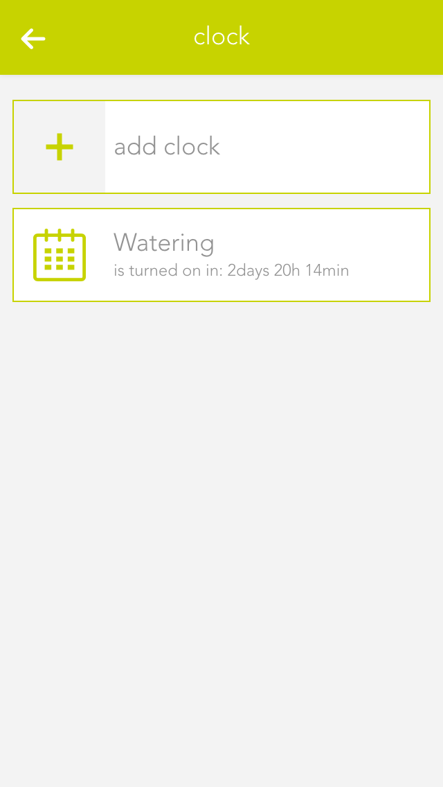
The first thing you need is a weekly programme. Create the weekly programme in the app “clock” and select “add clock”, then “weekly programme”. Next, name your weekly programme in the operator panel (e.g. garden irrigation).
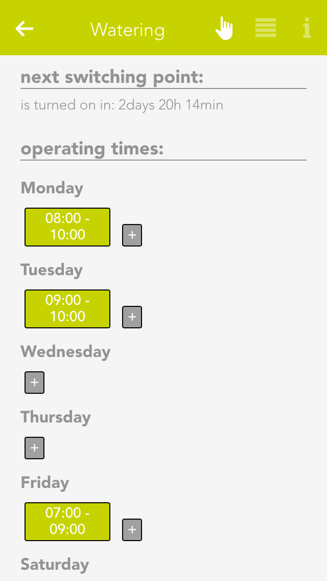
Now select the day the irrigation system should be active via the “+” button. In the window that opens, define the two times “from “ and “to”. This means the irrigation system should be active between these times (e.g. Monday from 8 am to 10 am). When you have done this, you can see the time until the next switch point at the top of the operator panel.
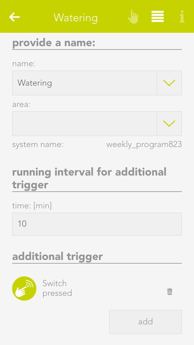
Once you have entered all the times when you want the irrigation system to be active, you can change to the parameter panel. If you wish the irrigation system to be active outside of the defined times, you can select under “additional trigger” the trigger that you want to also activate the irrigation system (e.g. a switch is pressed). In the item “runtime for additional trigger”, you need to define how long the irrigation system should be active if you activate it via a switch.
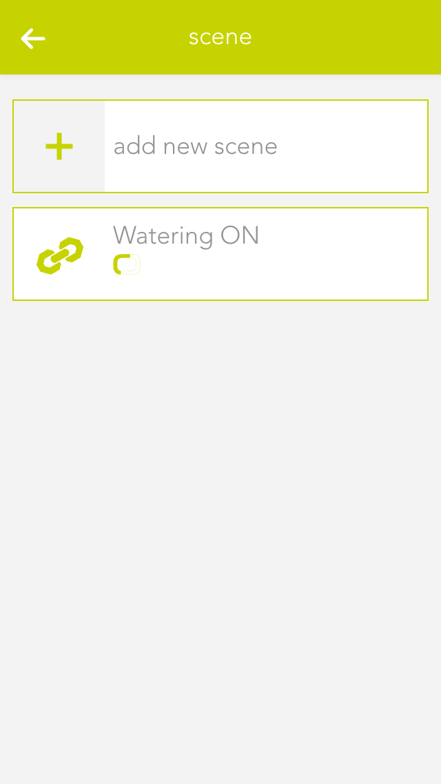
Now all you need to do is link the digital output with the weekly programme. You do this via a scene.
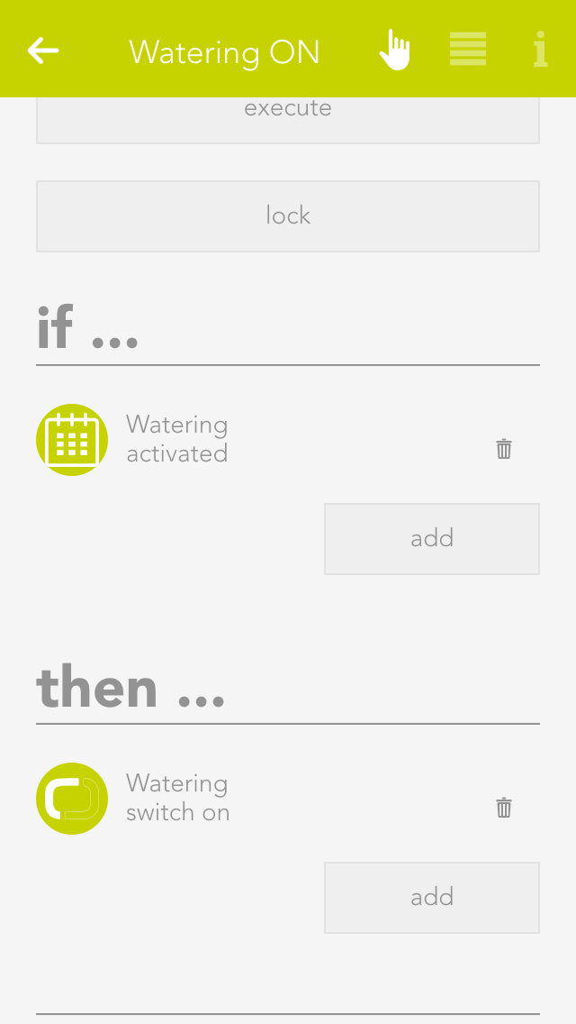
Create a scene, select “add” in the IF section and select your weekly programme, then click on “activate”. Select the digital output under “THEN” and select “ON”. Then create another scene and select the weekly programme for “IF” and select “OFF”
Now your garden irrigation system is ready. Make further adjustments to the weekly programme as required.
Extended Features
If the steps so far are not sufficient, you can adapt your evonHOME with further functions.
House Status
The “house status” displays the current status of your house and lets you change it.
The “house status” is located under “all apps” – “house status”.
Usage
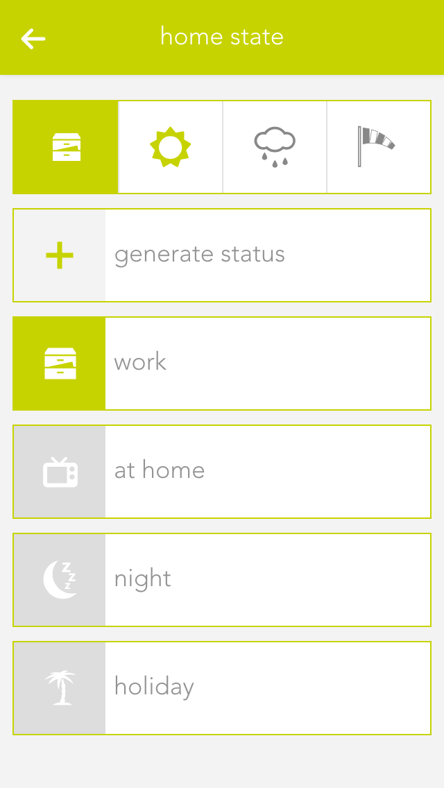
If you want to activate a status via the visualization, you can do this either in the left-hand area of the corresponding object panel or via the operator panel using the button “execute”.
The status that is currently active is displayed both in the object panel and in the house status panel. If you drag the house status to your favourites, then the current active status is displayed there too.
The house status panel not only displays the current status of your house, but also if dawn/dusk, rain or wind are active. You can configure where this information comes from in the “global settings”.
Create
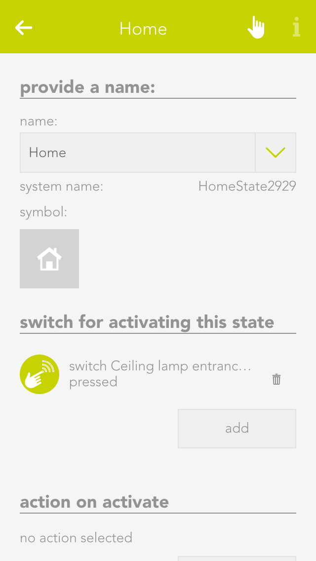
You can easily add a new status for your evonHOME. To add a new house status, click on the element “create status”. The operator panel opens and lets you first allocate a name to your house status. Once named, you can then continue with the configuration (described below).
Each status can be given a name and an icon that is displayed in your evonHOME.
Configuration
For each of your created house stati, you can define which button activates it and should happen if the status changes.
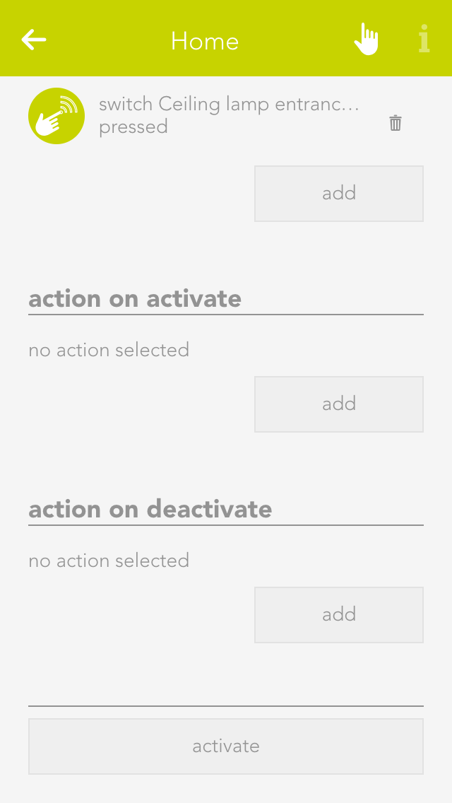
Button to activate this status
Select the button here that allows you to activate the corresponding status
Action when activated
Select here the action that is to be invoked when the corresponding house status is activated.
Action when de-activated
Select here the action that is to be invoked when the corresponding house status is de-activated
Clock
The clock lets you create an alarm clock, a timer or a weekly programme. The next chapters explain how to use them.
The clock is located under “all apps” – “clock”.
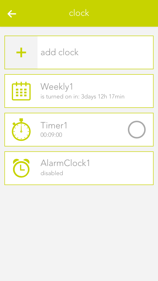
To create an alarm clock, a timer or a weekly programme, simply open the app “clock” and select “add clock”. A window then opens offering you a selection of elements you can create.
Alarm Clock
The app “alarm clock” lets you create an alarm clock that goes off at the time you define and is shut off after a certain time. An alarm clock is intended to be used with a scene to react to the alarm and the end of the alarm.
Using With A Scene

In order to use this alarm with a scene, it must first be named and then you can click on “add” in the scene’s “IF” and select the app “Clock”, unfold the alarm clock and select either “alarm triggered” or “alarm ended”.
Configuration

To define the alarm time, simply click on the currently defined time and select the time you wish for the alarm. You must also activate this alarm via the option “activate”.
The item “repeat” lets you select which on weekdays should the alarm be repeated. If you only want the alarm to go off once, select the option “just once”.

The length of time the alarm is active can be set under “extended” by activating the option “activate extended settings”. You will need the active alarm time if you want the alarm to last for a specific time. For example, if you have activated the alarm for 8pm with an active time of 10 minutes, then the alarm is active from 8 pm till 8:10 pm and then switches itself off. If you haven’t activated this option then the alarm stops directly after the trigger.
Timer
The app “timer” lets you define a countdown that, once the defined time has expired, can invoke a scene. You can also allocate a signal light to this timer that signals when the time has expired.
Operation

To adjust the time, click on the currently defined timer for this timer in the operator panel under “operation” and change it as you require.
The button “start” is used to start the timer and “reset” to reset the start time. The button “pause” stops the timer and you can continue the timer by pressing “start”.
Using With A Scene

In order to be able to use this timer with a scene, it must have a name. Then you can select the trigger “time expired” in the scene under “IF” and the appropriate action to be carried out when the timer has expired. You can also use the timer in the scene for the “THEN”. This lets you start, stop or reset a timer via a scene.
Configuration

Once you have allocated this timer a name and optionally a room, you can begin with the configuration.
You can add as many lights as you want in the item “signal light” using the button “add”. These lights are intended to flash on and off and the number of flashes can be set via the option “number of flashes”. The duration of each flash can be set via the “duration of signal flash”.
Weekly Programme
The app “weekly programme” lets you define up to 3 time periods per day in which you can execute actions. In order to be able to carry out an action, a scene must react to the activation and de-activation of the weekly programme.
Using With A Scene

In order to be able to use this weekly programme, you must give it a name. Once done, you can select the triggers “activated” and “de-activated” in the scene’s “IF” statement. For example, if a time from 9 am to 10 am has been defined for each Monday, then “activated” is invoked at 9 am and “de-activated” is invoked at 10 am. Furthermore you can use the weekly programme in the scene for “THEN” by selecting “switch on once” (“switch on once” is explained in the chapter “configuration”).
Creating And Editing Entries
To create an entry in the weekly programme, click on “+” for the desired day. This opens a window where you can configure the entry. You have the following possibilities:

Day
The weekday for which this entry is to be created.
No end time
If you only want to define a start point then activate this option. If a point has no end time, then the weekly programmer is activated after the time for the “runtime for additional trigger” has expired (located in the parameter panel).
From
This is the start point for your entry
Until
This is the end point for your entry
To edit an entry, click on the previously created entry (in the operator panel) and then proceed the same as for creating the entry.
Configuration

Runtime for additional trigger
If the weekly programme is activated once via the additional trigger, then the weekly programme remains active for the defined time. If you have an entry without end point, then the weekly programme also remains active for this time after the defined time has expired.
Additional trigger
You can add as many additional triggers as you wish that trigger the weekly programme once.
Weather Station
The evonHOME weather station is a simple way to receive local weather data and use it in your evonHOME.
The app “weather station” is located under “all apps” – “weather station”.
In order to use this weather station, open the global settings (“all apps” –“settings” – “global settings”) and drag the weather station to the first position for wind, rain, outside temperature and daylight (it is also possible to only use the weather station for wind).
Create
To use the evonHOME weather station, follow the following steps:
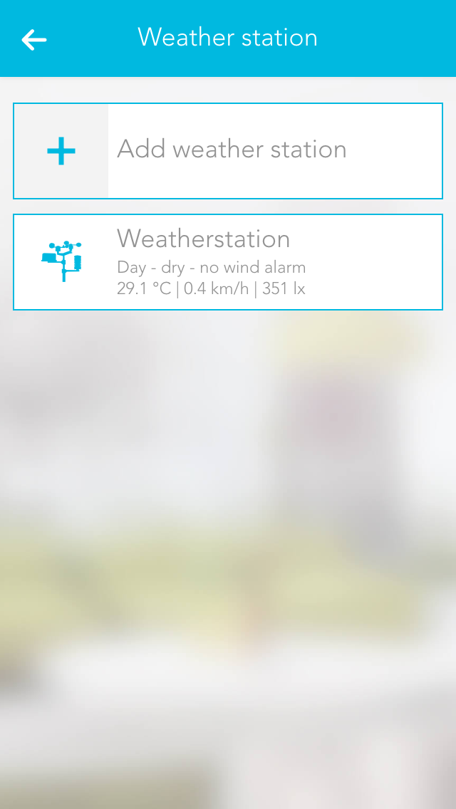
Mounting
Mount the weather station following the documentation (follow the instructions concerning the direction and distances carefully)
Connecting
Connect the evonHOME weather station 2-wire bus cable to the evonHOME CPU iX800 – ensure the polarity is correct (A-B) (recommended cable J-Y(ST)Y 2 x 2 x 0,8).
Power supply
Supply the evonHOME weather station with power (see documentation).
Add
Add a new weather station. If you have done everything correctly, a connection is established and your weather data are updated every second.
Note: Only one weather station can be operated by the CPU iX800.
Configuration
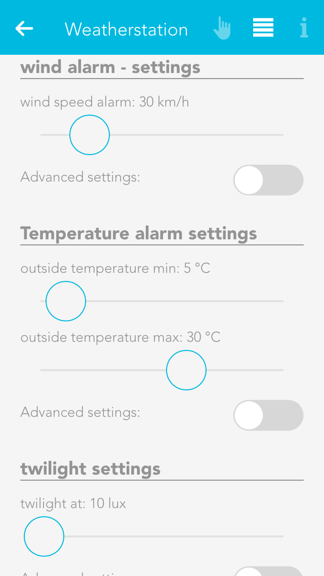
Wind alarm settings
The wind alarm settings let you define a wind speed above which an alarm is triggered. You can also define hysteresis so that the wind alarm does not trigger and end continuously should the wind speed oscillate around the alarm value. If you want that the wind alarm is active only after a certain time, then you need to enter a delay. This means that this time must be longer than the time set for “wind speed alarm”, so that a wind alarm is triggered.
Dawn/dusk settings
These settings let you define the light levels when dusk/dawn is active and inactive. Hysteresis and delay have the same functions as described previously.
Internet Weather Station
The Internet weather app lets you call up data for a specified region and use it for your evonHOME.

The app “Internet weather” is located under “all apps” – “Internet weather”.
Create
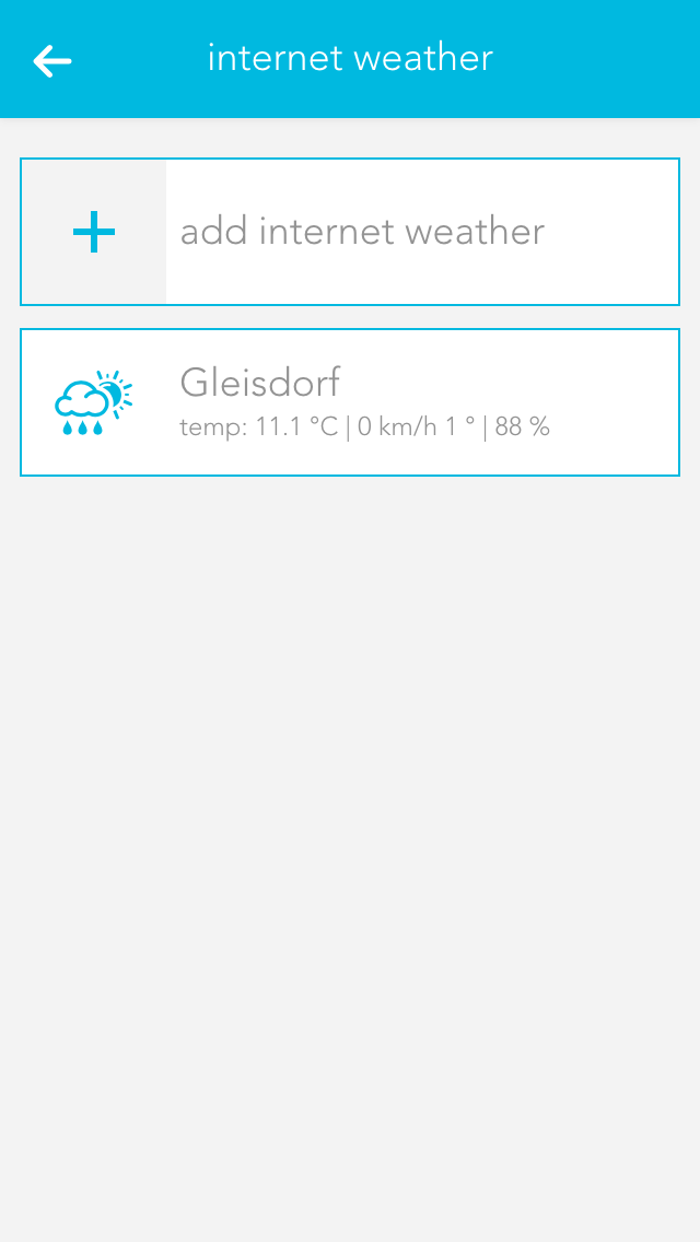
Click on the element “add weather station” to add a new weather station. This opens the operator panel where you need to define a name for your weather station. Enter the API key and your location in the item “weather underground API key”. This is provided by WeatherUnderground (http://www.wunderground.com) once you have registered there. Once you have done this successfully, you will receive weather data for the specified location.
If you want the use this weather station for your evonHOME, then drag this weather station to the first position for wind, rain, outside temperature and daylight in the app “global priorities”. (For example, if you only want to use the outside temperature of this station, then only drag the weather station to the first position for the outside temperature).
Configuration
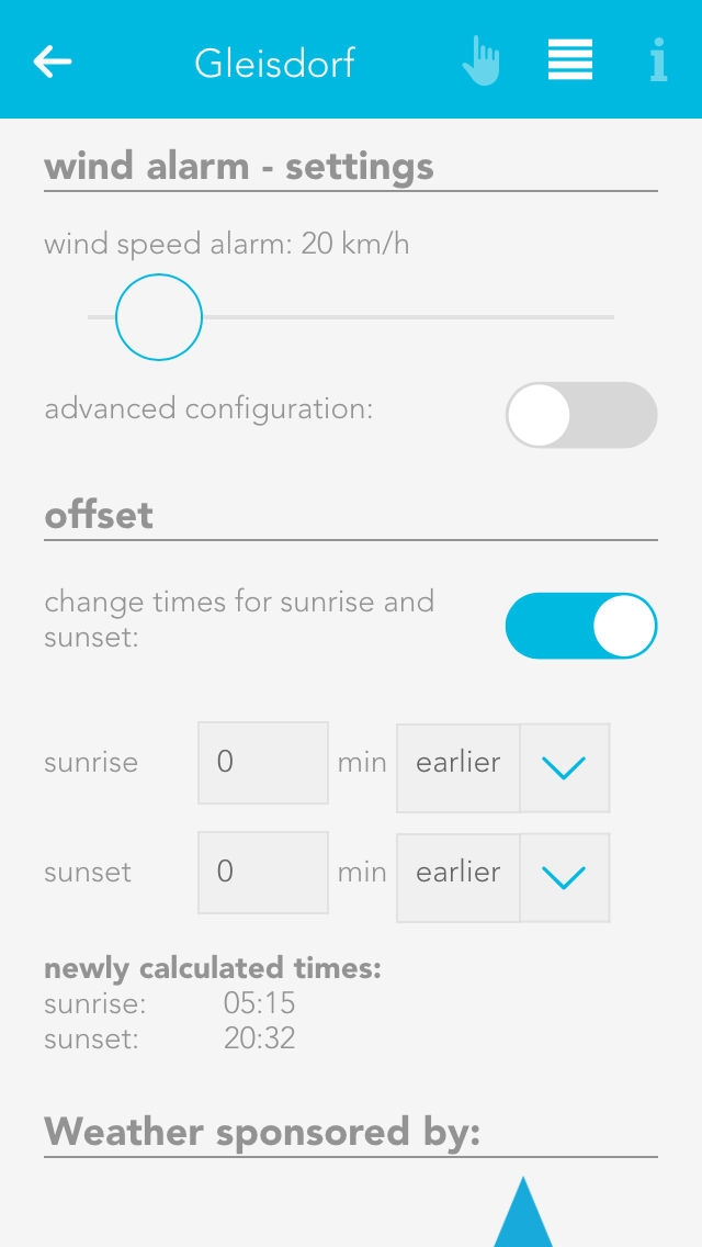
Wind alarm settings
This is where you define the wind speed that you wish to trigger an alarm. If you also wish to define hysteresis and a delay, then activate the option “extended settings” and select hysteresis and delay. If the wind speed exceeds the value defined for wind alarm, then the alarm is triggered. Now the wind speed must fall below the defined hysteresis value (below the wind speed alarm value) for the alarm to be reset. The delay defines how the wind speed must be above the defined limit for the alarm to be triggered.
Offset
If you are not satisfied with the time for sunset and sunrise, you can change then by activating the option “change sunrise and sunset times” and changing the times accordingly.
Door
The app “door” lets you create a door for your evonHOME. You can link a camera, a bellring button, a bellring and a door opener contact to such a door.
The app “door” is located under “all apps” – “door”.
Operation
If you open the operator panel for your door, then you can see the camera image (if a camera is linked to this door) and a button “open door” that lets you open this door (if a door open contact has been selected).
As soon as someone rings the bell for this door, you will receive a notification and a photo is taken of the moment the bell was rung that you can see when you open the notification.
Configuration
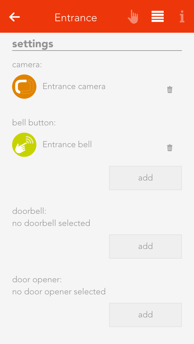
Camera
This field lets you select a camera for this door. The camera image is then always displayed on the operator panel.
Bellpush
Use the button “add” to add one or more buttons you wish to use to ring the doorbell.
Doorbell
Select the digital output that is connected with the doorbell.
Door opener
Select the digital output connected to the door opener using the button “add”.
Signal light
If you in a room where it is not possible to hear the doorbell, you can select a light in this room that will flash when someone rings the doorbell
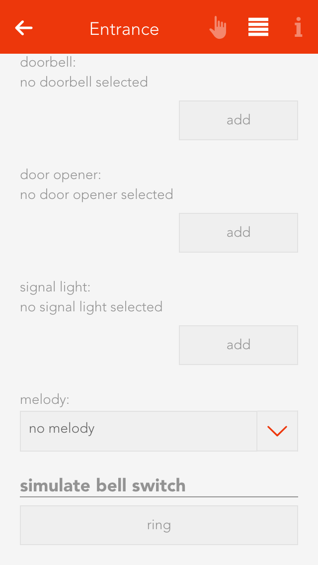
Number of flashes
Define the number of times the signal light is to flash when someone rings the doorbell.
Signal light on time
Defines how long the signal flash is to be.
Door open time
Defines how long the door remains open, if you open it via the app.
Doorbell time
Defines how long the digital output for the doorbell is to remain active.
Melody
If you want a melody to play on your smartphone, or tablet etc. when someone rings the doorbell, then you can choose here between two melodies.
Simulate
You can simulate the doorbell button press using the button “ring” to test whether you have satisfactorily configured all options according to your requirements. This has the same effect as if someone had really pressed the doorbell.
Window
The app “windows” lets you operate and configure all windows in your system. You also have pre-defined central functions such as “open all windows” and “close all windows”.
The windows app is located under “all apps”.
Window Settings
You can configure general settings for all windows in the window settings area located under “all apps” – “settings”.

Notifications of open windows and rain/wind
If you wish to receive a notification if a window is open and it is raining or is windy, then you must activate this option.
The item “open windows” shows you a list of all open windows. The button “update” reloads the list of all open windows.
Types Of Window
You have the possibility of integrating two types of window into your system, by window contacts or electric windows.
If you have simply just one window contact connected to a digital input, then you must create a “window contact”. However, if you have an electric window that you wish to integrate into your system, then you must create an “electric window”. Electrical windows are connected to blind modules, since they work according to the same principle.
Window Contact
Create
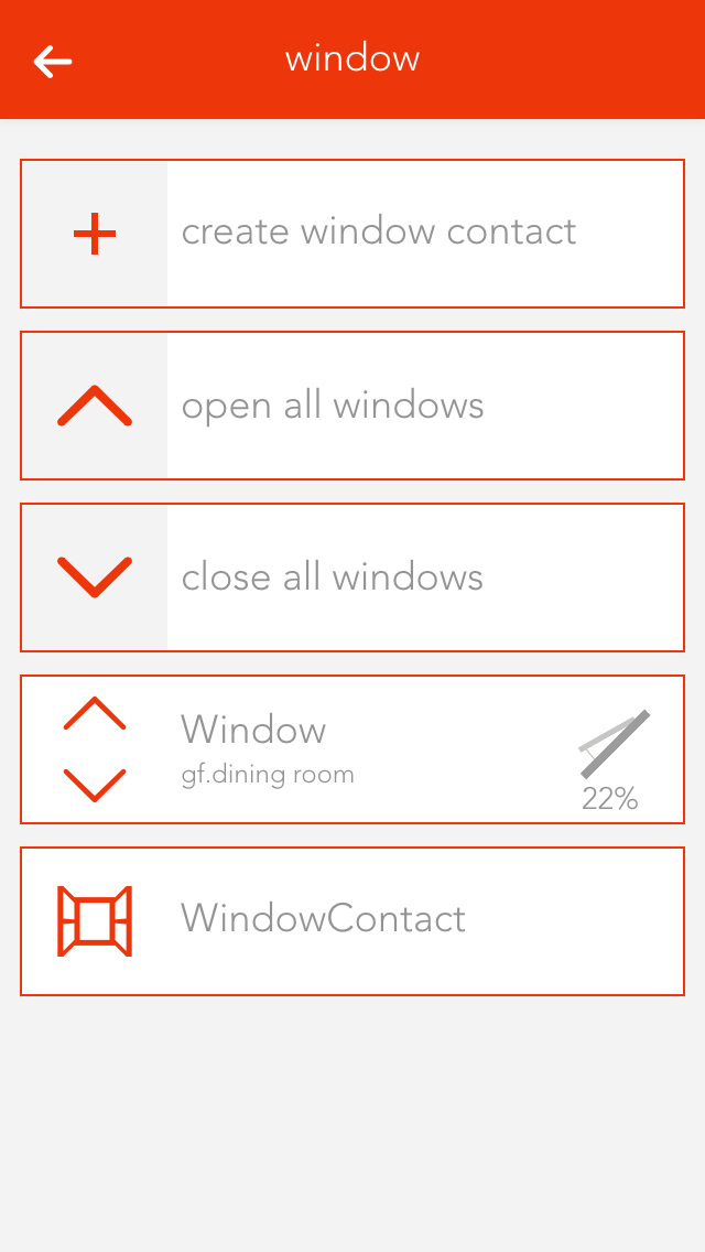
To create a window contact, open the window app under “all apps” and select “create window contact”. This opens the operator panel and the newly created window contact. It is important to first give the contact a name and optionally the location of the window.
Configuration
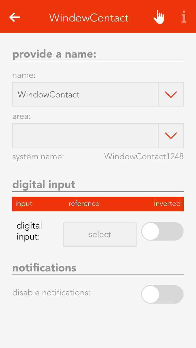
Select the digital input the window contact is connected to in the item “digital input”.
The object panel for this window contact will display whether this window is open or closed. If “open” and “closed” are reversed, i.e. the object panel shows a window to be open although it is actually closed, then activate the option “invert” in the operator panel.
You can de-activate notifications for wind and rain in the tem “notifications”.
Using With A Scene
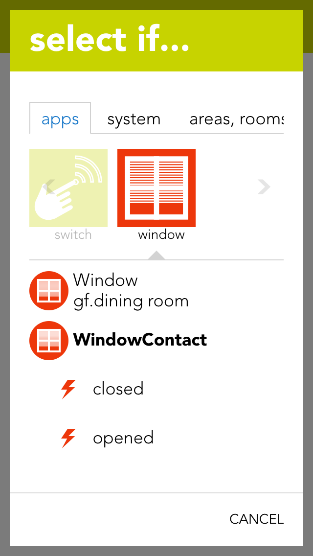
A scene lets you react to the opening and closing of a window by selecting the triggers “has been opened” or “has been closed” in the “IF…” statement and then selecting what should happen in the “THEN ..” statement.
Electric Window
Create
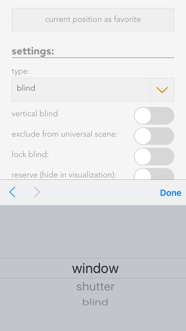
To create an electric window, open the app “shading” and select the blind the window is connected to. Navigate to the parameter panel and select the “type” “window”.
Operation
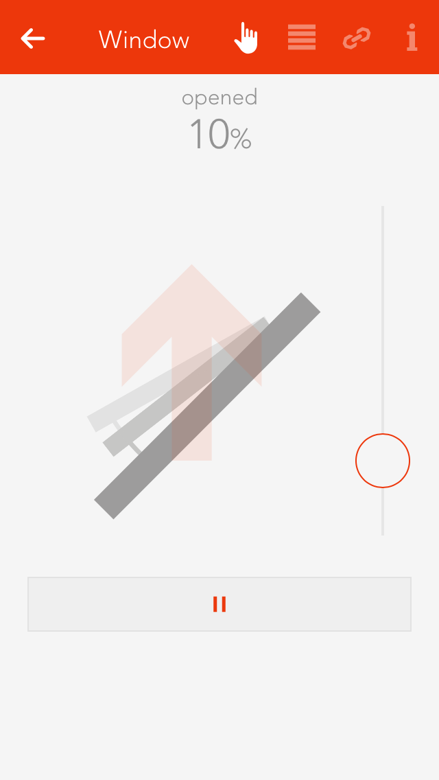
You can operate an electric window either via the object panel using the arrows on the left-hand side or via the operator panel using the buttons and the slider.
Adjust Opening Times
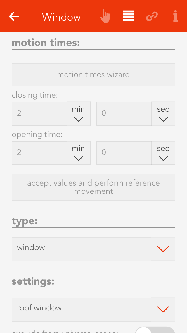
If you know exactly how long your window takes to open and close, then enter the times directly into the fields “closing time” and “opening time”, then click on the button “use values and run reference”.
If you do not know the times, simply use the wizard to determine the opening and closing times. Follow the wizard’s instructions and the times will be automatically entered and a reference activity carried out.
Configuration
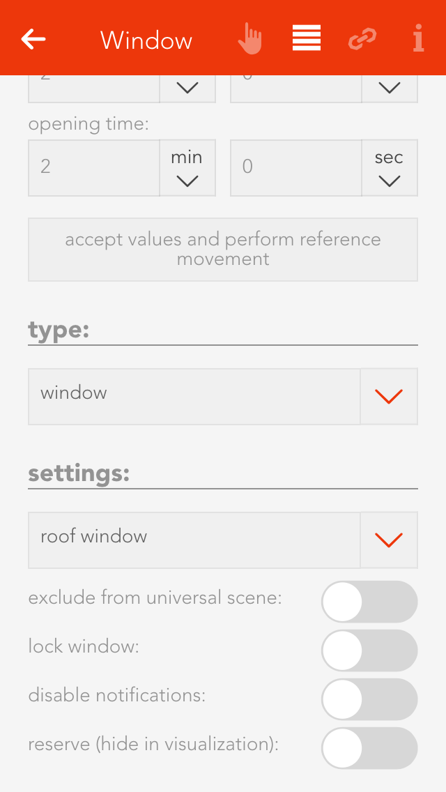
Type
If you want to convert this electric window back into a blind, then you can easily do this by selecting the type “blind”.
Except from universal scene
A universal scene “open all windows”, for example, would open all windows. However, if you wish a window to be excepted from this universal scene, then activate this option.
Lock window
This option lets you lock a window, i.e. the position cannot be changed, neither via the visualization nor via a button.
Deactivate notifications
If you do not wish to receive notifications for this window, then activate this option.
Reserve (hide in visualization)
“Reserve” lets you hide unused channels. You can unhide them via the app “hardware” and the corresponding module.
Couple With

If you want two windows to always have the same position, this can be done by coupling them. Simply select the button “select” in the item “couple with” and choose the window you wish to couple this window with.
Using With A Scene
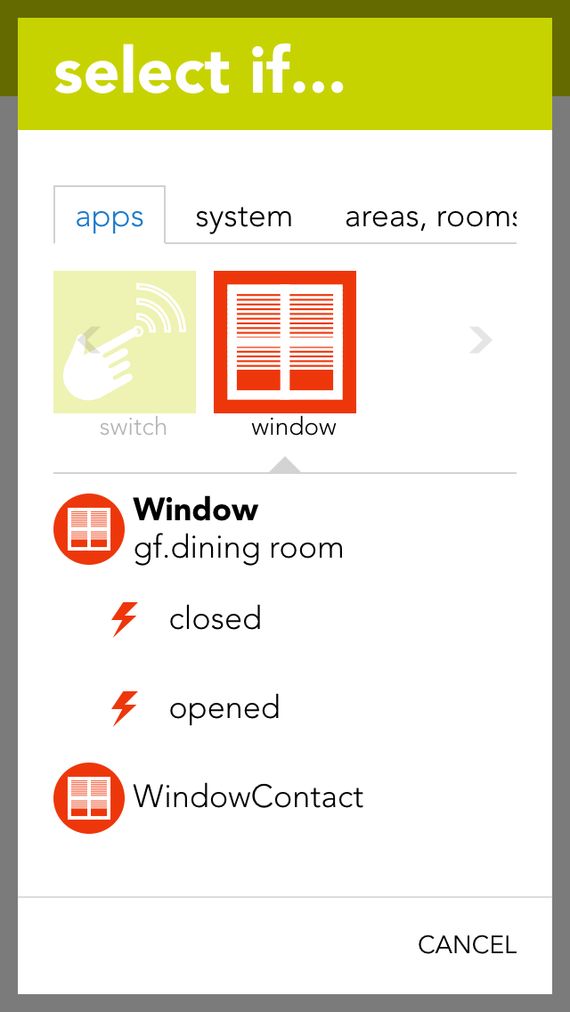
A scene lets you react to the opening and closing of a window in that you select “has been opened” or “has been closed” in the “IF” statement and then select what should happen as a consequence in the “THEN …” statement.
You can also select the actions “go to position” (go to a window position you have defined), “open” and “close” in the “THEN” statement of a scene.
Alarm System
The app “alarm system” lets you create a personal alarm system for your evonHOME. The alarm system is divided into a central alarm system and one or more alarm groups. Alarm groups divide the alarm system into several areas.
The app “alarm system” is located under “all apps” – “alarm system”.
Operate
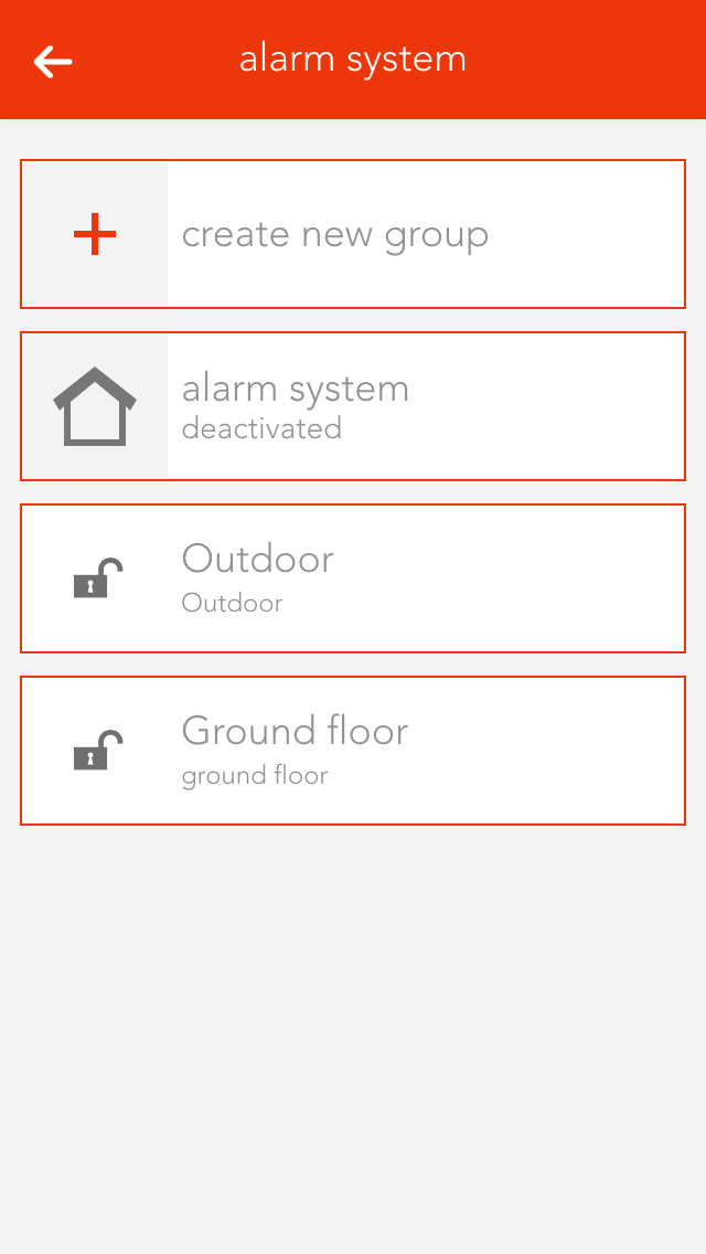
If the alarm system or one or more alarm groups have been activated, the defined activation delay for each alarm group must first expire before the alarm can be triggered. Once the activation delay has expired, if a movement detector is triggered then a trigger delay is activated. During this time, the alarm system can be de-activated without an alarm being triggered. Once the trigger delay has expired, the silent alarm is triggered and a notification is sent. Once the silent alarm time has expired, the actual alarm is triggered and a further notification is sent and the outputs linked to the alarm system are switched.
Activation time is necessary for the following situation: you want to leave the house and activate the alarm before you go. To make sure that you do not inadvertently trigger the alarm yourself, you need the activation delay.
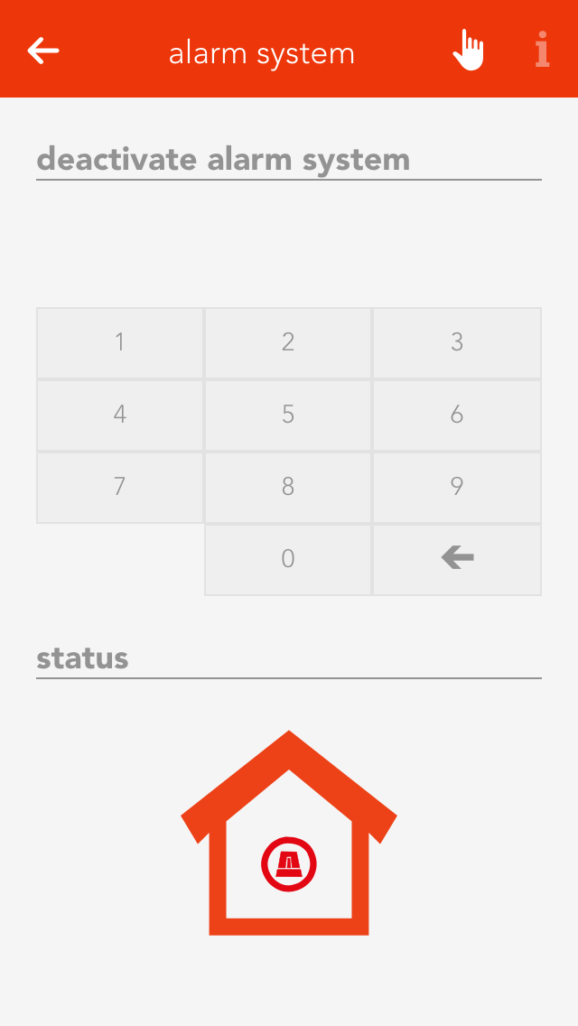
If you want to activate the alarm system, you can either do this via the app by opening the alarm system (“all apps” –“alarm system”) and select the button “activate” in the operator panel for the alarm system, or you define a button to activate the alarm and you use this button (how you do this is described in the chapter configuration). Deactivating the alarm is done the same way via the app, only that you have to enter a password. Deactivation via a button works identically to activation.
Warning, since the alarm system can be deactivated without a password using a button, you need to select a button that is not immediately visible!
Configuration

Duration of silent alarm
Enter the time for silent alarm here.
Automatically deactivate alarm after
Automatically deactivates the alarm after expiration of this time. This is important if you are holiday and something triggers the alarm. If this option was not available, the alarm would never switch off and your neighbours would not be too pleased with you.
Duration of patrol
This is the time the alarm should be deactivated for while you make a patrol.

Button to activate the alarm system
Select a button to activate the alarm system.
Button to deactivate the alarm system
Use the button “add” to select a button to deactivate the alarm system. Warning! This button can deactivate the alarm system without a password. Consider the use of such a button carefully.
Button to start patrol
Select a button to let you start a patrol.
Button to end patrol
Select a button to tell the system you have completed your patrol.

Status light
Select a light that will flash twice when the alarm system has been activated and once when deactivated.
Actions when alarm triggers
Use the button “add” to select all the actions you wish to happen when an alarm is triggered (e.g. switch lights on, activate siren, etc.).
Actions when alarm stops
Select what should happen when the alarm is deactivated. Caution! Do not forget to deactivate the actions started when the alarm was triggered.
Change password
Change the password to deactivate your alarm system.
Alarm Group

Bathroom Heating
“Bathroom heating” lets you configure suitable heating systems and control their times.
These functions are located under “all apps” – “bathroom heating”.
Operation
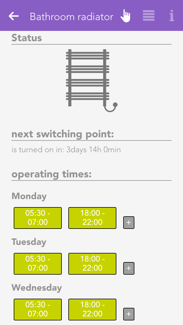
To add a new bathroom heater, click on the element “add”. First allocate a name to your bathroom heater in the parameter panel, then you can continue with the configuration (described below).
Configuration
You can determine what time each of your bathroom heaters should be on. You do this by defining the operating times in the operator panel. You can define one or more time intervals where your heater should heat for each weekday.
Apart from the operating times, you can also define a button to activate each bathroom heater, where it is connected and whether it should be switched into maintenance mode.
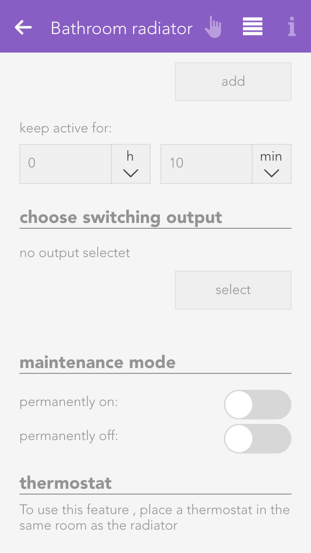
Additional trigger
Select the trigger and the duration for which the bathroom heater should additionally be activated for a short period of time.
Select socket
This lets you define which socket your bathroom heater is connected to.
Maintenance mode
This lets you permanently switch the maintenance mode for the bathroom heater on or off.
Circulation Pump
“Circulation pump” lets you configure and control the times for suitable pump systems.
These functions are located under “all apps” – “circulation pump”.
Operation
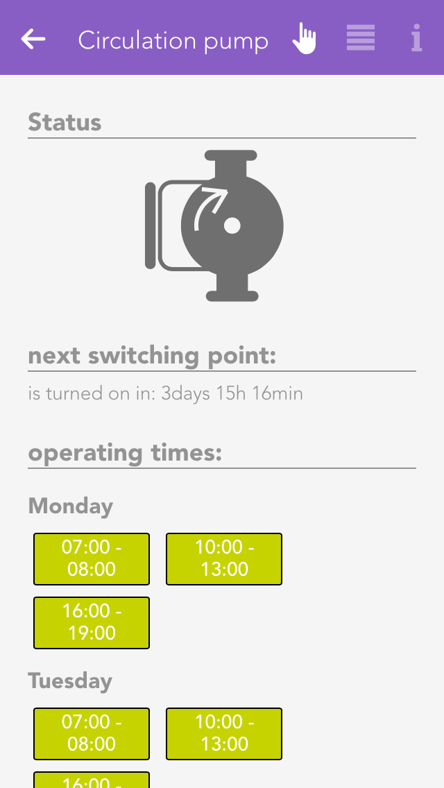
To add a new circulation pump, click on the element “add circulation pump”. The next step is to allocate a name for your circulation pump in the parameter panel. Then you can continue with the configuration (described below).
Configuration
You can define the operation times for each one of your circulation pumps. This is done by defining the operating times in the operator panel. You can define one or more time intervals for each weekday when you wish the circulation pump to be in operation.
In addition to the operating times, you can also define intervals within the operating times, which trigger activates them, where they are connected and whether they should be put into maintenance mode.
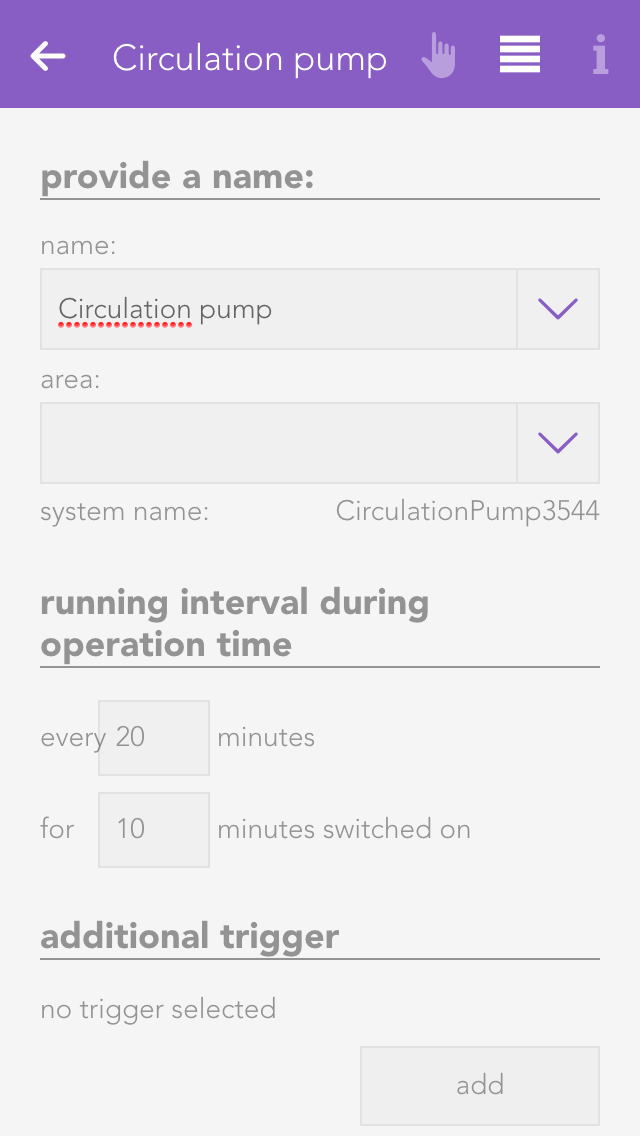
Active interval during operating time
Define the intervals within the operating time you wish to circulation pump to be active.
Additional trigger
Select the trigger and the duration for which the circulation pump should be additional active for a short period of time.
Select socket
Define which socket the circulation pump is connected to.
Maintenance
Switch the circulation pump permanently on or off for maintenance purposes.
Mixer Circuit Control
The “mixer circuit control” app is an external temperature heating control loop. The “mixer circuit control” is used to configure and control 3-way heating mixer valves.

These functions are located under “all apps” – “mixer circuit control”.
Operation

Click on the element “add mixer control” to create a new mixer circuit controller. The next step is to give your mixer circuit control a name, and then you can continue with the configuration.
The operator panel displays a schematic of the control. This diagram shows you whether the pump is on (screw in the pump is green and rotates) or off. Displayed adjacently is the current temperature of the feed line and to the right the current position of the mixer valve and whether it is open or closed.
All relevant values pertaining to your mixer circuit control are displayed below this.
If your mixer valve is unreferenced, i.e. the current position of the valve is unknown, then the button “execute reference” is displayed. Clicking on it closes the valve completely; hence the current position is known. The mixer circuit control must be fully configured before a reference can be executed.
Heating Curve
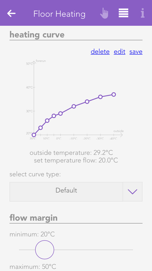
The heating curve allows you to adjust the desired temperature of the feed line as a function of the outside temperature.
There are pre-defined curves you can select from using “select curve type”. If there is no pre-defined curve that entirely suits your needs, then you can edit the pre-defined curves by clicking on “edit”. The selection then jumps to “user-defined”. If you wish to save your curve, click on “save”. Saved curves can be deleted using “delete”. When selecting points, you are limited on the one hand by the minimum and maximum feed line temperature, and on the other by the previous and subsequent point. For example, the point at 10 °C outside temperature cannot have a lower feed line temperature than the point at 15°C and a higher temperature than the point at 5°C.
If the outside temperature reaches a value outside of the curve, then the curve is continued horizontally. This means if the curve were to end on the left-hand side at an outside temperature of +20°C with a corresponding feed line temperature of +22°C, then the feed line temperature for outside temperatures higher than +20°C will remain +22°C.
To be able to process outside temperatures higher than +20°C, the cooling operation must be activated under “all apps” – “settings” – “room climate”. Warning! Cooling operation may only be activated if the heating is really able to cool, since in cooling mode, the mixer outputs are switched exactly the opposite way.
Feed Line Temperature Limitation
You can define your minimum and maximum feed line temperatures here.
Mixer Parameters
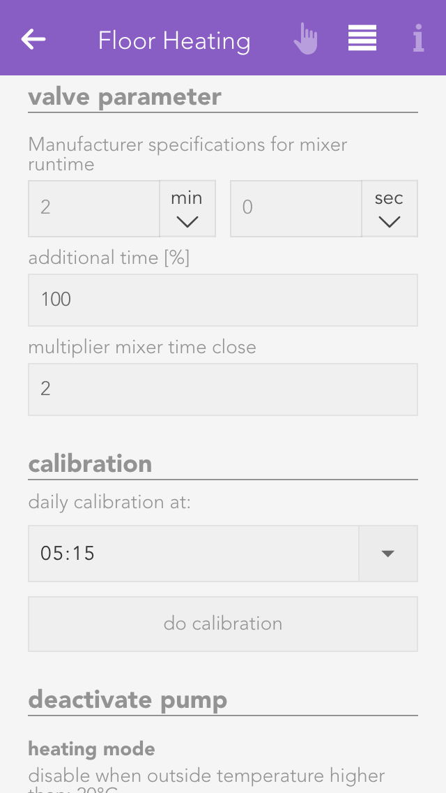
Enter the runtime for the mixer valve in seconds according to the manufacturer in “manufacturer mixer valve runtime [s]”. If the value you entered was correct, then you must now click on the button “execute reference run”. Please note that you must have previously correctly set the inputs and outputs.
The field “overrun time” lets you how much longer in percent the mixer output remains switched on when completely open or closed. This guarantees that the mixer is subsequently really completely open or closed.
Since a mixer valve normally requires longer to close than to open, you can use the “multiplier mixer closed” to define how much longer the valve needs to close than open.
Calibration Run
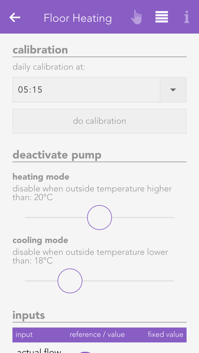
Since there is always a certain error when opening and closing the valve, a calibration run must be run daily. All you have to do is set the desired time for this to occur and the rest is done automatically.
Inputs
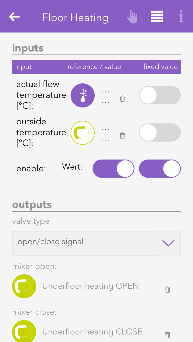
Feed line actual temperature
Select the input here that measures the actual temperature of the feed line.
Outside temperature
Select here the input used to measure the outside temperature. The standard setting is located in “system” – “house status” – “outside temperature”.
Release
Select the main switch for the mixer control. This input is used to activate or deactivate the entire control.
Outputs

Mixer open
Select here the output used to open the mixer valve.
Mixer closed
Select here the output used to close the mixer valve.
Pump
Select the output used to connect the mixer pump.
Fault
Select an output to be switched if there is a fault.
Extended Configuration
The extended configuration allows you to configure all the components of your mixer control extra. Simply click on “edit”. Exercise caution, particularly when adjusting the controller parameters.
Below this, you can adjust the sample time and minimum error.

Sample time
This is the time period when a new position of the valve is calculated (standard 10s).
Minimum error
The position of the valve is only adjusted if there is a difference between desired and actual temperature of the feed line. If the difference (error) is larger than this value, then the position of the valve is changed.
Activate notification
If you wish to receive a notification of a fault condition, then activate this option.
Logic
The logic app enables you to execute complex operations for which there is no app. For example, this could be controlling the ventilation of the WC, controlling a light transformer etc. If you wish to use logic, then you should already have a basic understanding. If you are new to the area of logic, exercise caution when using this feature.
The logic app is located under “all apps” – “logic”.
Logic Program
To create a logic sequence, you first need a logic program. This is comparable to a network in PLC programming. A program contains logic elements that you can use for your controller. For example, if you have a controller for the WC ventilation and one for a light transformer, then you can create an individual program for every controller.
Create
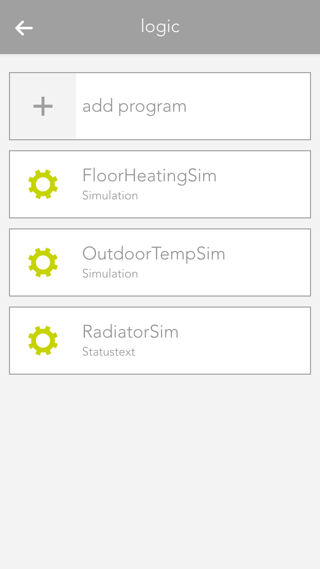
To create a logic program, open “logic” and select “add program”. This opens the operator panel for the logic program. You must first allocate a name to your program and optionally a room for it.
Parameter
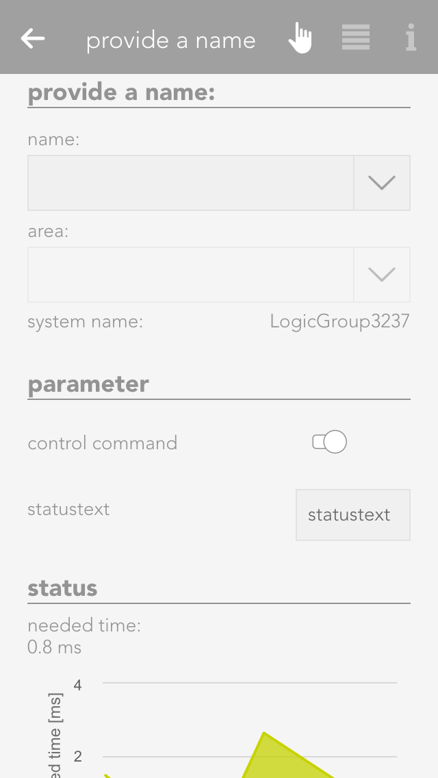
The operator panel for the logic program contains an item “parameter” where all parameters available to rapidly configure the program are listed (parameters are described in the chapter data elements). The values of these parameters are not lost if a controller fails.
Status
The item “status” displays a diagram that shows you the time required to execute this program.
Control Command And Status Text
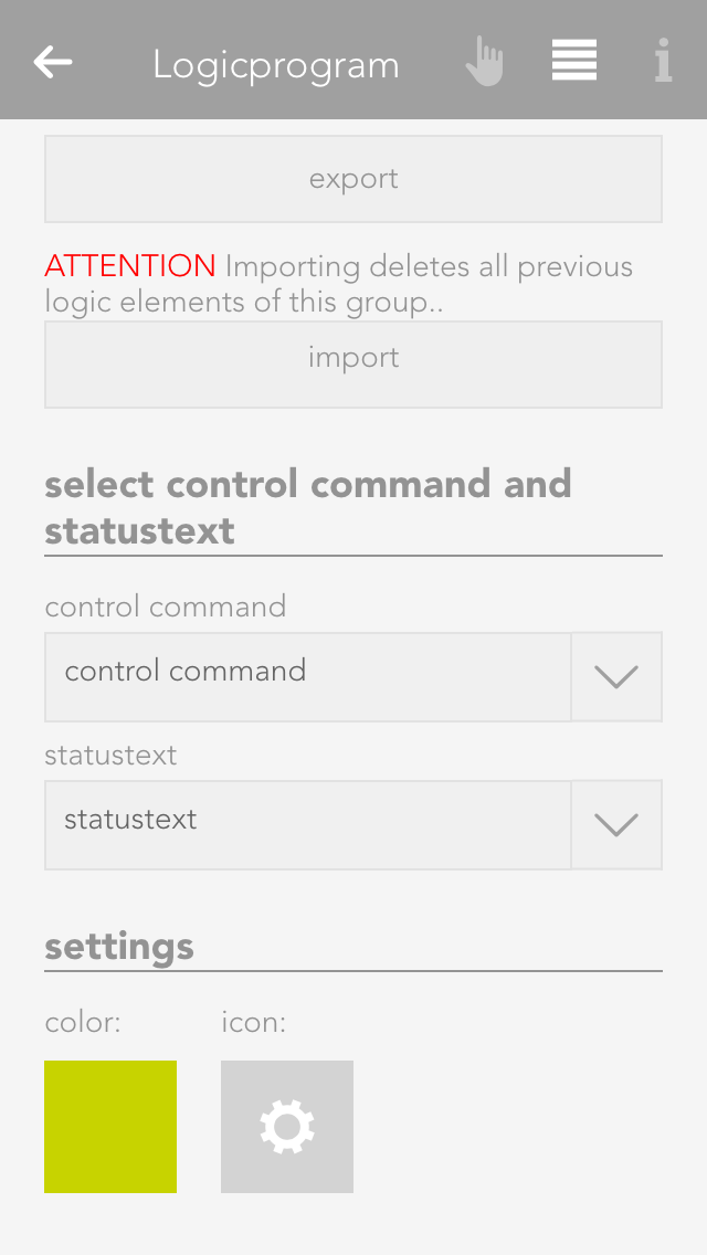
Every logic program can contain a control command and a status text. You can select a data element of type bool for the control command and a data element of type string (text). To do this, go to the parameter panel and select “choose control command and status text”.
The control command is intended to activate and deactivate the logic program via the object panel. You can toggle the control command via the icon on the left-hand side of the object panel.
The status text is displayed in the object panel under the name of the program. An example would be “ventilation will be switched off in 2 mins”.
Edit Logic
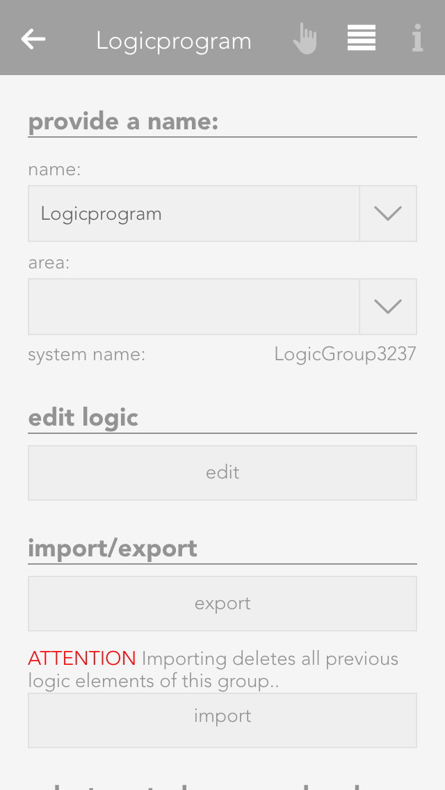
If you want to edit the logic in this program, click on the button “edit” in the parameter panel under the item “logic”.
Import/export
If you wish to save the logic program, you can do this via the button “export” in the parameter panel under the item “import/export”.
To import a logic program, click on the button “import” (directly under the “export” button). Note that any existing logic is overwritten by the logic in the imported program. Furthermore, if logic elements were linked across programs prior to export, after importing, the links no longer exist.
Color And Icon
You can allocate a colour and icon to your logic program. Do this in the parameter panel under the item “settings” by clicking on the current colour or icon.
Logic Elements
Elements are all logic elements that you can add to a logic program (AND, OR, etc.)
Create
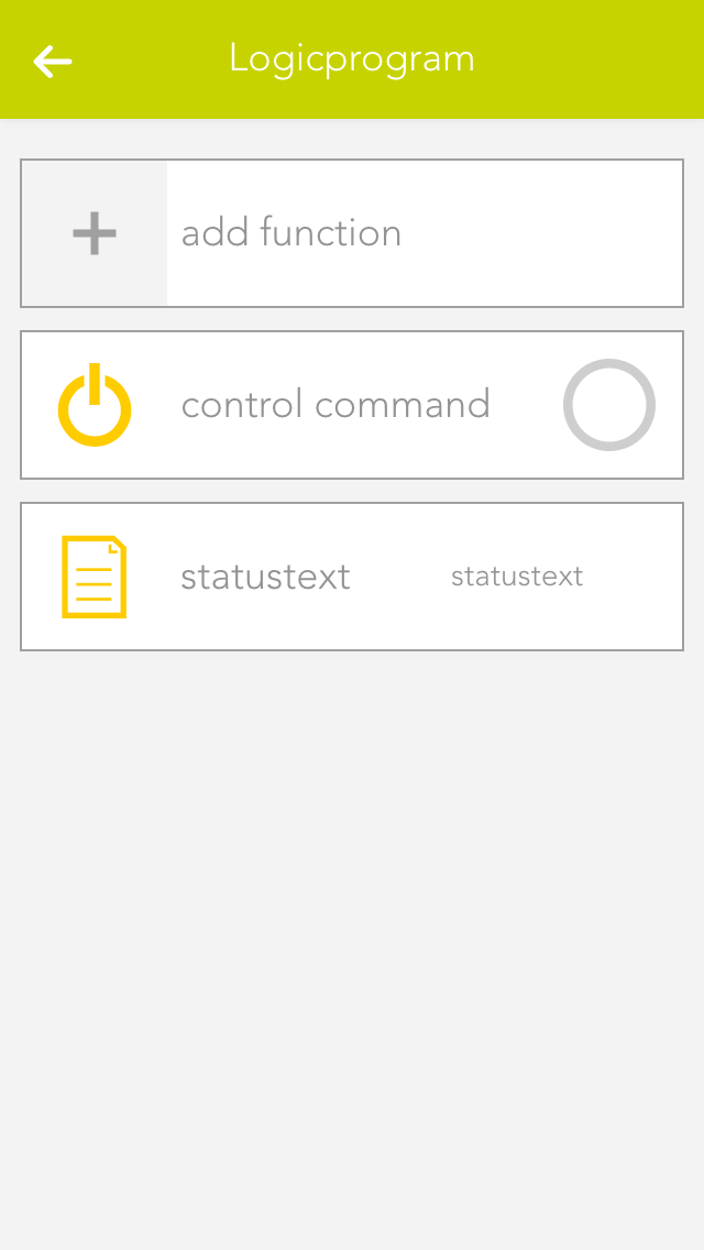
To create a logic element, you must first be located in the logic program. If not, open the logic program and select the item “edit logic” in the parameter panel. Then add new logic elements to the program using “add function”. To do this, click on the corresponding element.
Element Colour
If a logic element has an error, or if it is simply not activated, then you can recognize this due to the colour of the element.
Green
The element is working fine.
Orange
The output of this element is being simulated.
Grey
The element does not have a fault, but it is deactivated.
Red
The element has a fault: either an input has no value, or the output it is linked to no longer exists.
Connecting Elements
The operator panels for each logic element (except for data elements) are all constructed using the same principle. The first item is the setting (if available), then the inputs, then the output.
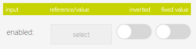
This shows you the selection of an input.
The button “select” lets you select the output of a different logic element that you wish to connect to this input.
The checkbox under “invert” lets you invert the input (if it is of type bool).
The checkbox under “fixed value” lets you allocate a fixed value to the input. This means that if you activate this checkbox, the type bool displays a checkbox in the centre with the text “value”. The state of the input can be controlled using this value. If you activate this checkbox for an input of data type number or string, then an input field appears where you can enter the desired value.
Data Elements
Data elements are intermediate stores for values. This means that data elements can be described by other logic elements by selecting this data element at the output (however only if both are of the same type). Data elements can also be linked with inputs of other logic elements. Every data element has the option “parameter” in the operator panel. If you have activated this option, then you can see this data element in the operator panel of the corresponding logic group and you can change it from there. This has the advantage that you do not always have to have the logic program open to change a value. Parameters also means that the value of a data element remains even if the controller were to fail.
You can change the value of any data element via the object panel. You can do this on the left-hand side of the object panel for types bool and number, and on the right-hand side via the input field for type string.
AND
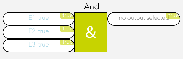
The element “AND” is a classical AND operator. This means the output is set to true as soon as ALL inputs are true. This element can have between 2 and 6 inputs. The number of inputs can be changed via the operator panel using the buttons “add pin” and “remove pin”.
OR
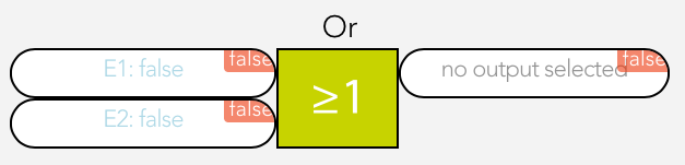
The element “OR” is a classical OR operator. This means the output is true as soon as at least one input is true. This element can have between 2 and 6 inputs. The number of inputs can be changed in the operator panel using the buttons “add pin” and “remove pin”.
Compare
The compare function works by comparing the values present at the two inputs and switches the output accordingly.
You can change the following settings in the operator panel:
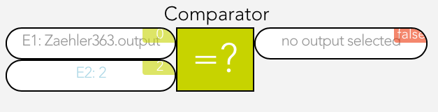
Type
Select the type of comparison
Hysteresis
If you require hysteresis, you can define it here.
Sample time
This is the time for which the comparison must be fulfilled for the output to be switched to true.
Time Relay
The time relay lets you delay an output switching on or off, or leave it switched on for a certain time.
The time relay has two types that you can configure under “select used times”.
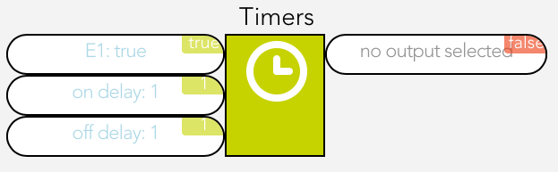
Delay switching on/off
If the input is true, the output is only set to true after the selected ON time delay. If the input jumps from true to false, the output is set to false after the selected OFF time delay.
Switch on delay and duration
This enables the option “input as flank”. If you have not activated this option, then the input must be true for at least the switch on delay time in order for the output to be set true for the defined duration and after this duration (independently of the input) reset to false. If you have activated this option then a flank is sufficient on the input and the output is set to true for the defined duration and then reset to false.
Time Measurement
Time measurement is represented by a stopwatch. Time measurement can be started, stopped and reset via inputs “activated” and “reset”.
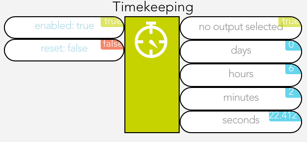
If the input “activated” moves from false to true, the stopwatch starts. If the input “activated” moves from true to false, the stopwatch stops, if “auto reset” was NOT activated.
If “auto reset” is activated, then the stopwatch is reset when the input “activated” moves from true to false.
The input “reset” resets the stopwatch. This only works if “auto reset” has not been activated.
Value Allocation
Mit der Wertzuweisung kann ein beliebiger Wert dem Ausgang zugewiesen werden.
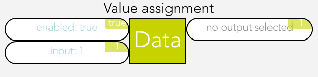
The value on the input E1 is written unchanged to the output if “activated” is true.
Counter
The counter can increase, decrease or reset a numerical value to 0.
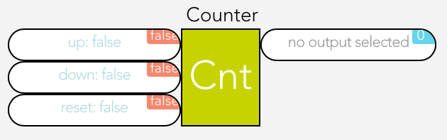
The input “up” increments the counter by one when the input changes from false to true, the input “down” decrements the counter by one and “reset” resets the counter to 0.
Flank Recognition
Flank recognition allows rising and falling edges to be evaluated. This means that if the selected flank appears on the input, then the output is set to true for one cycle and then reset to false.
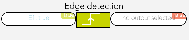
The type of flank can be selected in the operator panel under the item “settings”.
Function Generator
The function generator enables periodic square wave signals to be generated.
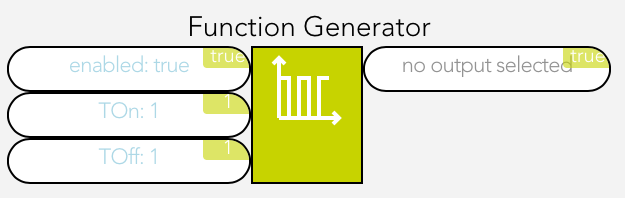
As soon as the input “activated” is true, the function generator is started and generates a periodic square wave signal on the output.
“TOn” can be used to adjust how long the square wave signal is true and “TOff” how long it is false.
Function
A function element is used to carry out mathematical calculations. “A1” must contain the desired calculation.
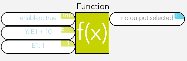
The variables E1 to E6 can be used for the calculation, e.g. A1 = 2*E1 + E2.
As soon as the input “activated” is active, the calculation will be carried out. The buttons “add pin” and “remove pin” can be used to add up to 6 inputs. The following shows link shows you which operations are possible:
Documentation- Functions(https://developer.mozilla.org/de/docs/Web/JavaScript/Reference/Global_Objects/Math)
Reset
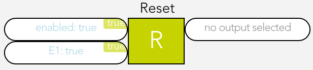
For as long as the input is true, the output of the reset element will be set to false.
Set
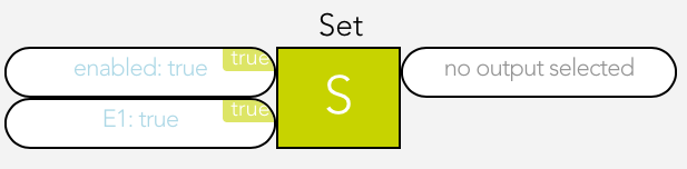
For as long as the input is true, the output of the set element will be set to true.
SR Flip Flop
The SR flip flop is used to set and reset an output. If the input “set” is true, then the output is true. If the input “reset” is true, the output is false. If both inputs are true, then the output is false. If both inputs are false, the output is stored, meaning it remains in this state until the input is true again.
Text Block
The text block is used to create any text string you want.
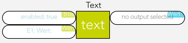
1 to 6 inputs (E1 – E6) can be created using the buttons “add pin” and “remove pin” and the text from these inputs are then strung together.
For example, if the text for E1 is “It is now ” and the text for E2 is the current time (use the button “select” and under “system” then “time”), then the following text string will be created “It is now 17:00”.
PI Controller
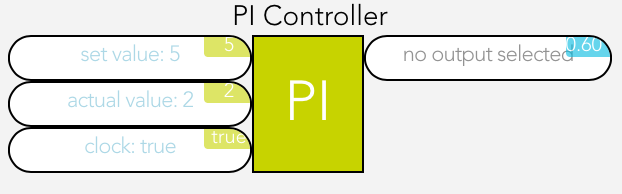
This is a clocked PI controller where you supply demand value, actual value and clock.
The settings for the PI controller are located in the parameter panel.
Examples
WC Ventilation
Task
If the light in the WC is switched on, then the ventilation should be switched on 15 seconds later (the ventilator must be connected to a digital output) and run for one minute after the light has been switched off. If the light is switched off before the ventilator is switched on, the ventilator should not be activated.
Solution
First open the app “logic” and create a logic program via “add program”.
Give the logic program the name WC-ventilation and select the room WC.
Open the logic program via the button “edit”. Use the “add function” to add the function time relay. This relay is red, meaning that it isn’t yet working, because there are no inputs.
Now open the time relay. Since the output should be switched on after 15 seconds, you will need a delay of 15 seconds. Change the switch on delay to a fixed value and enter the value 15. Do the same for the switch off delay, except instead of 15, use the value 60, since the ventilation is only meant to run for 1 minute (= 60 seconds) after the light has been switched off.
Now you need to link inputs and outputs. Select input E1 using the button “select” and navigate to the lights, select the WC light and select “light on”. In the object panel of the time delay, you can now see the current value of the light and how it changes when the light is switched on and off. Now all you need to do is connect the output of the time relay with the digital output. To do this, click on “select” under “output” and navigate to the digital outputs. Once there, select the desired output and click on “set value”.
Now you can test your WC ventilation and see if everything is working fine.
Light Transformer
Task
There are 4 lights and 1 light transformer available. The light transformer is connected to a digital input. As soon as at least one light is switched on, the light transformer must be switched on. If no lights are switched on, the light transformer must also be switched off.
Solution
The first thing to do is open the app “logic” and create a logic program via “add program”.
Give this logic program a name “light-trans”.
Next, open the logic program using the button “edit”. Use the button “add function” to add an OR. This OR is red meaning that it is not currently functioning, because it has no inputs.
Now open the OR and add two inputs using the button “add pin”. These four inputs must now be linked with the four lights via the button “select” by selecting “light switched on” for each light. The OR is now green, because all inputs are linked. Finally, you need to connect the digital output of the transformer with the OR. Do this by clicking on “select” under “output”, open the digital output there and select “set value” for the desired digital output.
The logic should now work as desired.
Ventilation Control
Task
You measure humidity in a room and want to switch on the ventilation as soon as the humidity has reached a certain value.
Solution
To do this, the humidity sensor must be connected to an analog input of an analog module and configured accordingly (to do this, see chapter “Analog Input”). The ventilation must be connected to the output of a digital module.
Next, create a logic program in the app “logic” using “add program”. Give the program a meaningful name (e.g. fan control) and if wish, allocate a room. Then open the parameter panel and select “edit” under “edit logic”. Insert a compare function via “add function”.
Now open the operator panel of the compare function. Under the item “settings”, first select for “type” the value “greater than” (since the fan is to be switched on when the humidity is GREATER than a certain value). You can configure the hysteresis for the compare function as you feel is necessary. In this example, select 5 for the hysteresis. The sample time can be left at 0. Now the compare function is correctly configured.
The inputs and output now need to be connected. Select the analog input you connected the humidity sensor to under “inputs” for “E1”. For “E2” enter the value above which the fan is to be switched on. In this example select 80. Now select the digital output you connected the fan to using the button “select” under “output”.
The ventilation control is now complete. If you want, you can change the hysteresis and the sample time as you require.
Camera
The app “Camera” lets you integrate your evonCAM into your system.
The Camera app is located under “all apps” – “Camera”.
Create

In order to create a camera, click on the box “add new evonCAM” inside the app.
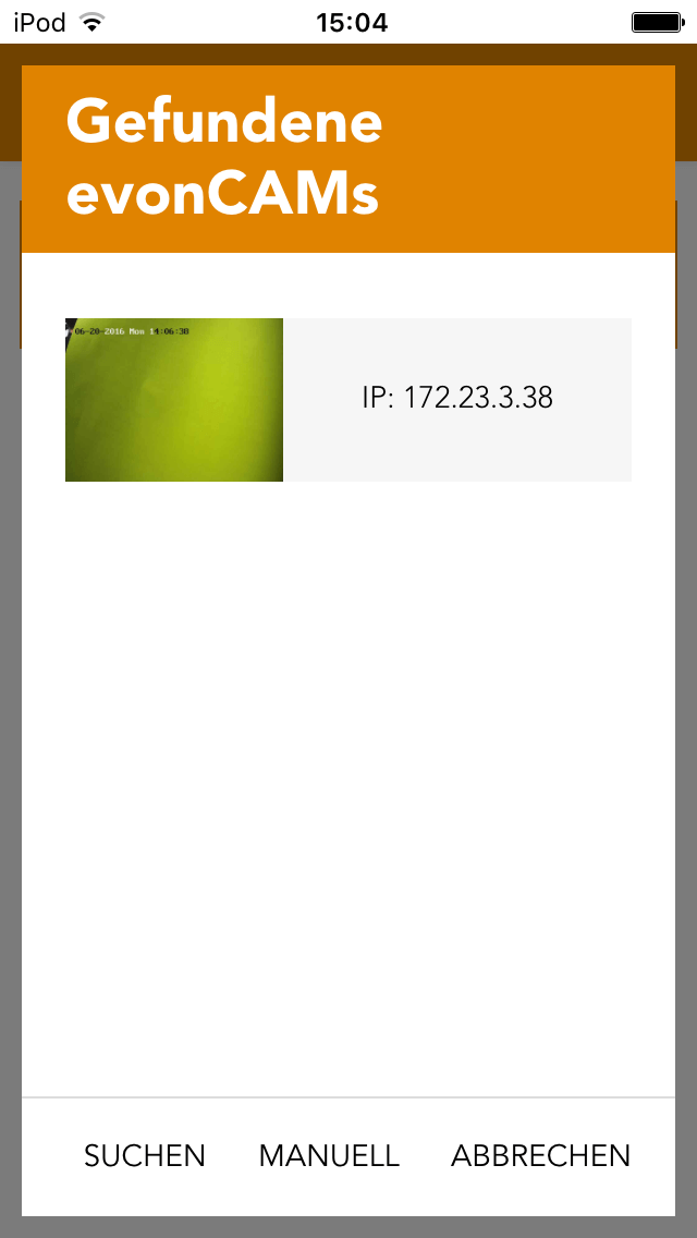
All found evonCams including a preview image will now be listed in the popup which appears. Once your camera shows up on this list you can select it and it will be added to your system and is ready to be used.
If your camera ist not immediately found in your network, you have the option to restart the search or to configure it yourself. In this case a camera will be added for which you have to add the required settings (IP address, username, password).
Configuration
To correctly configure the camera, enter the IP address of the camera into your browser.

If you followed the steps to integrate your evonCAM and the camera was found and added to your system, no further configuration is required.
In case you chose the manual configuration (e.g. because the camera was not automatically found in your network), you can change or adapt the required settings at any time in the ParameterPanel of the camera.
This can also be necessary, when you make changes to the standard username/password or the IP address.
If you change the settings (username/password) of the camera (via its webinterface) the app or browser may ask you to enter the new credentials.
After you did this, it is important to go to the ParameterPanel of the camera and update those settings there, otherwise you will regularly be asked to enter the new credentials.
Operation

The camera panel supports two different sizes. If you hold down your finger (cursor+left mouse button) on the panel for some seconds a bar will appear on the bottom of your screen, which gives you the ability to change the size from small to large.
The large size supports displaying the current camera video inside the panel. Like most other panels, you can add this to your favorites on the start screen which will allow you to always see the current camera image.
With the icon located on the top right corner of the camera image, you can open a popup with bigger view of the video stream, which is well suited for bigger screen sizes like tablets.

The camera OperatorPanel displays the current video/image if the correct credentials are added in the settings. You can also open a popup containing a bigger sized version of the camera image by clicking the icon in the top right corner of the image.
If you did not enter a name for the camera yet, the associated input field will also appear here.
Denon
This section contains information on using connected DENON devices.
Denon lets you play music throughout your house, whether from a USB stick, music server, Internet radio, iPod, AUX or online music.
The Denon app is located under “all apps” -“Denon”.
Currently, only the DENON DRA-N4 amplifier is supported by evonHOME.
Operation
Volume
You can change the volume via the “+” and “-“ buttons, or use the slider.
Source
Use this to determine where your music is to come from and see the Denon display below it. Navigate around your Denon using the 4 arrows and the enter button.
Favourites
Add the current programme to your favourites list using the button “add to favourites” so that you can find it again quickly. All your favourites are displayed in a list below this.
ON/OFF
Switch your Denon on an off.
Status
Shows which music source is currently active, Internet music, iPod etc. and shows the current IP address.
In the parameter panel, you can also define whether this Denon is to be switched with the universal scenes or not “remove from universal scene”) and how loud the Denon can be allowed to be.
Linking
You can link the Denon to a scene. You have several possibilities.
Use the following if the IF statement
Pause
The scene is invoked when the sound is paused.
Play
The scene is invoked when the music begins, i.e. when the play button has been pressed.
The “THEN” can have the following triggers:
Switch off
The Denon is switched off as soon as the scene is invoked.
Switch on
The Denon is switched on as soon as the scene is invoked.
PlayMusic
The Denon begins play music at the start volume which then increases to the define target volume. The ramp-up time defines how long it takes to reach the target volume. The favourite number lets you choose which favourite you wish to play.
Fronius
The "Fronius" app allows you to integrate your Fronius system into your evonHOME.

The Fronius app ist located under 'all apps' - 'Fronius'.
All limits, which can be configured in the Fronius app, can also be used as triggers for scenes.
Create
To integrate your Fronius system, please follow the steps below.
(You will need the IP Adress of your PV-system for this)
Open the Fronius app an choose 'add'.

Enter the IP address of your PV system in the now appearing popup.
Confirm it with the button 'add'.
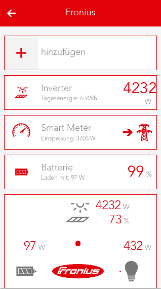
Once entered successfully, all installed elements of your PV system will be shown.
Elements
If you integrate a Fronius system, every installed element (which is supported by evonHOME) of your PV system will be displayed.
Additionally the Dashboard of the Fronius app can be extended with more panels.
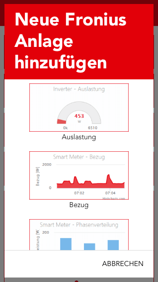
Once a PV system is integrated, you can choose to add additional panels by using the 'add' button.
You can choose between 'My Fronius', an overview about the current energy flow in your system, "Efficiency" (of the inverter), “Energy“, "Supply" and "Phase Distribution".

There is also a dynamic diagram available, which can be customized by the user. It allows you to choose between different values and diagram types.
All panels can be added to the home screen by selecting them with a long click/press.
Inverter

Operation
The most important values are displayed in the first part of the detail view (Operator Panel).
Additionally, the utilization and energy values for year, month and week will be shown in a diagram.

Configuration
The second part of the detail view (Parameter Panel) allows you to view detailed values and and adjust limits. Three power limits can be set which will trigger an event once exceeded or below the set value.
Detail values
Lists values which can be used by an inverter in the system.
Scenes
The inverter offers an event for the power limits 1,2 and 3 in case they are exceeded (above/below).
Smart Meter

Operation
The operator panel of the Smart Meter displays the current feed-in/supply to or from the power grid and presents them in an area diagram.

Configuration
The parameter panel displays the phase distribution in a bar chart and allows you to adjust feed-in/supply limits for he power grid, which will throw an event once exceed (below/above). In addition, all detail values of the Smart Meter are displayed.
Detail values
Shows values which can be used by a Smart Meter in the system.
Scenes
The Smart Meter offers events for feed-in/supply to or from the power grid in case they are exceeded (above/below).
Batterie

Operation
The operator panel displays the current charging/discharging rate (in watt) and the current battery power level.

Configuration
The parameter panel allows you to adjust the minimum charging level, which will trigger an event in case it is exceed (above/below), and to view the detail values of the battery.
Detail values
Shows values which can be used by a battery in the system.
Scenes
The battery offers events for exceeding (above/below) the minimum charging limit.
TCP Client
The TCP Client app allows you to communicate with TCP-compatible devices (TCP clients). Among them are devices like beamers, TVs and many more. Additionally, you can use a gateway (TCP to serial port) to send commands to different devices with a serial port.

The TCP Client app is located under “all apps” – “TCP Client”.
Create

To create a new TCP Client, navigate to the app and choose 'add TCP client'.

On every TCP Client, there is a symbol which shows you if there ist a working connection to the desired device. As you have to configure every new TCP Client first, the symbol will display a red X.

Before the TCP Client can communicate, you have to enter a valid IP address in the settings. To do so, open the Parameter panel of your newly created TCP Clients and enter the IP address and the port of the desired device.
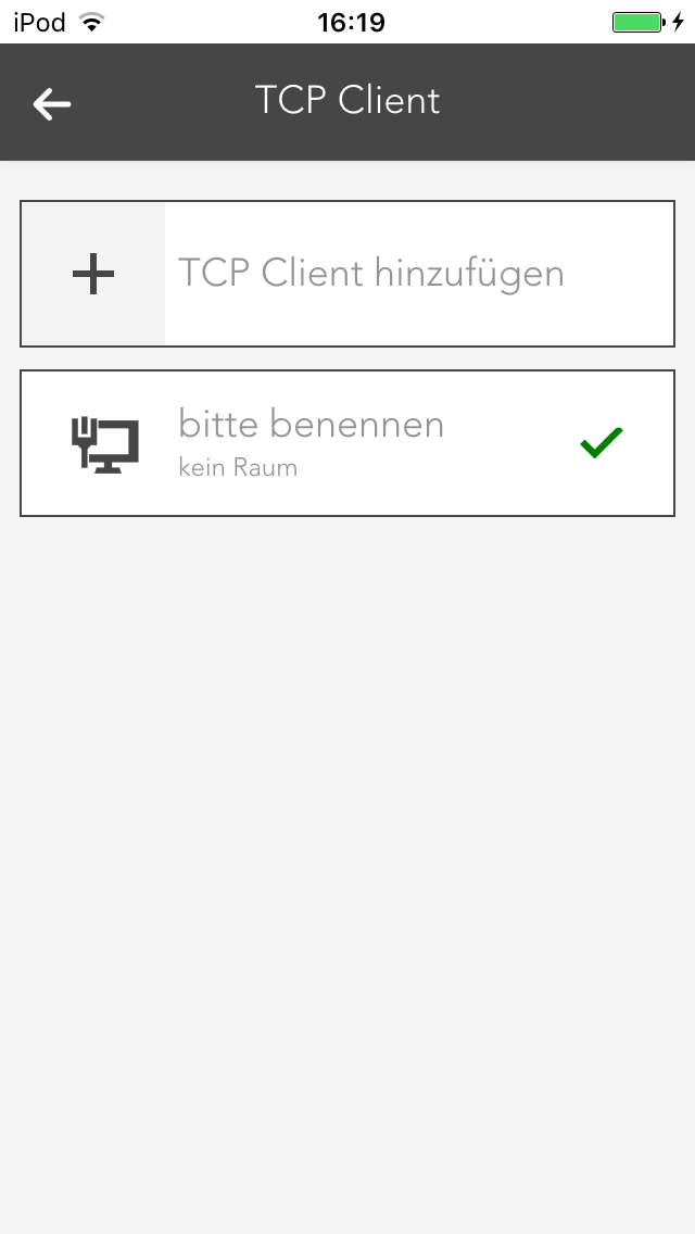
If the IP address and port are correct and a successful connection could be established, you will see a green checkmark in the display of the TCP Client after some seconds.
Operation
The Operator Panel of the TCP Client displays the current status of the client, allows you to send preconfigured commands and shows you a list of recently received data.

State
The current status of the TCP Client will be shown here.In case there are any problems with the connection to the desired device or you haven't entered a correct IP address yet, a red X will be displayed.
Events
Every TCP Client allows you to create 3 events, which are triggered when the conditions meets. You can then link to those events in created scenes (inside the Scene app) and use them as triggers. Configured events will be displayed in this list.

Commands
All commands you have created are listed here. You can trigger or delete each one.
Last received data
This list will display recently received data. You can switch between a 'text' or 'hex' view.
Configuration
The settings of the TCP Client allow you to configure new commands and events, which can be linked in scenes.

IP configuration
The IP address and port of the device for which you want your TCP Client to establish a connection to should be entered here. This settings should be the first configuration you make after creating a new TCP Client. The Operator Panel will then tell you if your connection is working.
Commands
If you want to create a new command, you can do this here by using the 'new command' button. Choose a name and the data which should be send. You can decide between simple text or hex values. Additionally, you can also decide whether you expect a specific answer and choose between text or hex values.
Test command
If you just want to test a command, you can do this here. The result will then be displayed beneath the 'test command' button.

Result
There are some devices, which may frequently send data, without the need for a explicit request (e.g. via a command). For such use cases, every TCP Client has 3 events. For each event, you can set what data you are expecting and their type (text or hex). If an expected event occurs this event will be triggered and can be linked to when creating a Scene.
Detector
The Detector app allows you to use a digital input for alarms/notifications. This can be useful in cases like when you want to connect a fire alarm to your evonHOME.

The Detector app is located under “all apps” – “Detector”.
Create
To create a Detector, you will need a digital module ("evonHOME Digital 1180" or "evonHOME Digital 1344") with an digital input. Then, follow these steps:

Navigate to the app 'Digital Inputs', which you can find under 'All Apps'.

Select the desired digital input, which you want to use as a Detector.
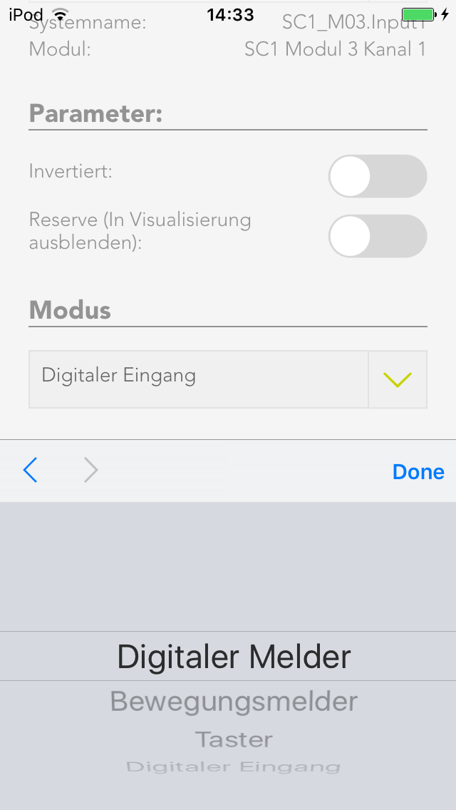
Navigate to the settings of the chosen digital input and change its mode to 'Detector'.

The Digital Input changed into a Detector and can now be found in the 'Detector' app.
Operation

After you changed a Digital Input into a Detector, it will react to incoming signals and trigger an alarm, depending on its configuration.
A detector will display if his input is currently active and if it is triggering an alarm.
Configuration
Each Detector allows you to configure the triggered alarms. Here you will find the description about all available options.

Type
This are pre configured settings for different use cases. Each one comes with a predefined notification text, settings and specific icon.
Alarm after
Defines the timespan for which a signal has to be active on the digital input to trigger an alarm.
Notification
Here you can choose to receive a notification once an alarm gets triggered.
Notification text
Set the text you want to see in the notification.
Alarm must be acknowledged
If this option is active, an active alarm has to be manually terminated instead of ending once the input signal stops.
Reserve (hide in visualization)
Once active, the Detector will be hidden in the visualization.

Icon
Defines which image should be used for this Detector.
Alarm Output
You can choose a digital output, which will be triggered in case of an alarm, here.
Mode
Here, the Digital Input which is used for this Detector can be switched back to another mode.
Simulation on
Activates the simulation and allows you to set a value via the setting 'Simulation Value'. Attention: If the simulation is active, real values are ignored!
Simulation Value
Change the simulated value with this setting.
Counter
This app is used when you connect a counter to a digital input. With it's help you can react to the signals send form the counter unit and evaluate them. For example, you can record a power consumption in kW, set various value limits and react to them later in scenes.

The Counter ist located under “all apps” – “Counter”.
The minimum pulse length for a counter connected to a digital module is 100ms. For faster counters, please use the input located on the cpu module.
Create
To use a counter in combination with the corresponding app, you will have to connect it to a digital input of your evonHOME (DI1 - DI4 on the CPU or 'evonHOME Digital 1180' or 'evonHOME Digital 1344'). Then follow these steps:
If you find not create a counter in your evonHOME system yet, you have to convert a digital input into one.

Navigate to te digital inputs in 'All Apps' - 'Digital Inputs', select the desired input and open the ParameterPanel.
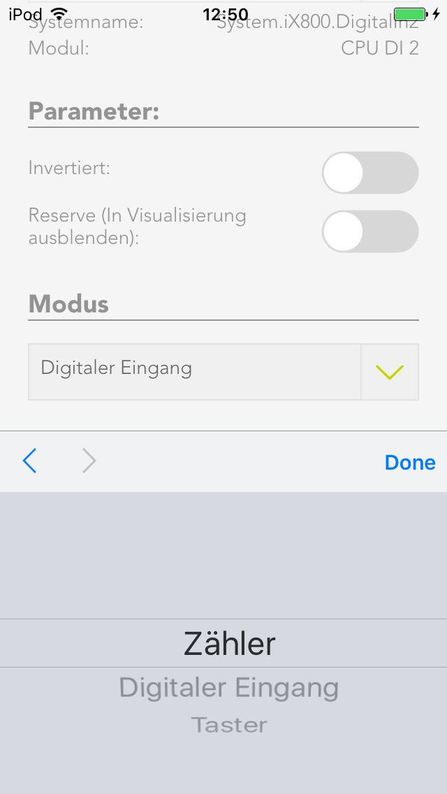
In the settings for mode, choose 'Counter'. The digital input will now be converted into a Counter an will be listed in the Counter app.
Configuration
Every Counter allow you to change certain settings, which determine what will be counted (e.g. kWh) and what limits exists.

Pulse value
Choose the significance of the impulse which gets received by the counter. The necessary settings for this are usually listed on the counter device.
Settings
Inverted
If this option is activated, only falling edges will be counted instead of rising edges.
Reserve
Hides this counter from the visualization.
Color
Changes the color of the visible graphs.
Edit count
Here, you can set the current count to a desired value

Show statistics
Choose the graph/chart, which will be displayed in the OperatorPanel.
Limits
You can choose various limits (and according delays) here, which you can then link in scenes. Linkable values are: 'current consumption - upper limit', 'current consumption - lower limit' and 'daily consumption - limit'.

Mode
With this setting you can convert/revert a counter to a digital input or switch
Operation

Once a Counter has been created, you can add additional visual panels. Those grant you an overview about the evaluated values.
To add such a panel, use the button "add panel".
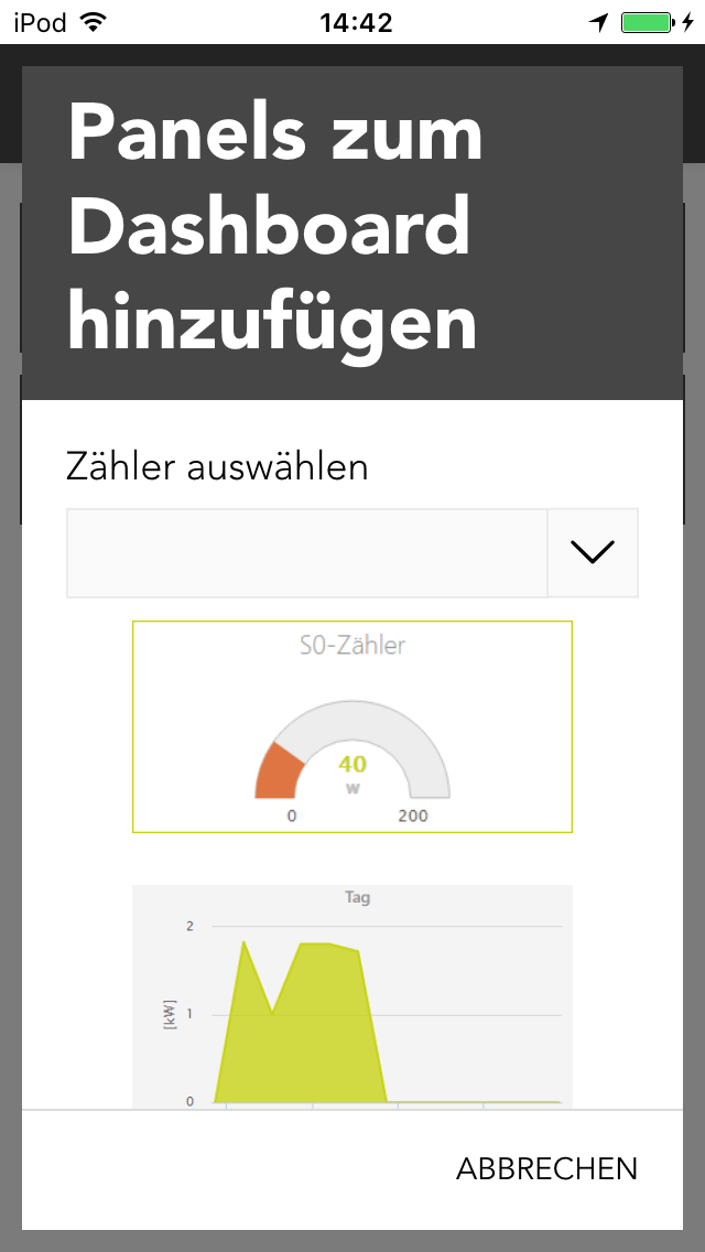
In the popup which will appear, you can choose between several graphs/charts. To do so, you have to select the corresponding Counter under 'choose counter' and then one of the desired charts.

The OperatorPanel gives you an overview about the measured values. The following sections exist:
Status
Gives you information about the total, daily and current consumption. In addition, you can also reset the counter.
Statistic
The graphs/charts which you can activate in the ParamterPanel will be shown here. The statistics which are shown here can also be reset with the corresponding button.
uLux
The app allows you to configure the evonHOME uLux switch.

The uLux app is located under “all apps” – “uLux”.
Important: To integrate the uLux switch into evonHome, the required uLux design-template must be present on it. In delivery state, all evonHOME uLux switches already contain this template. Further configuration with the uLux software is not required.
Create

To create a new uLux room, click on the add symbol, after which a search for uLux switches in your network is started. If the switch is not immediately found, you can just restart the search. Once the uLux is found, you just have to select it to add it to your system.
Operation
The uLux switch works like a room control. This makes it easy to add all elements from a room (lights, blinds, heating, scenes) to it.

Just add a name and room to your uLux switch and once you finish the configuration every element from this room will automatically be displayed on the switch.
Configuration
After the uLux switch has been found, you only need to add a name, a room and an IP-address.

Network configuration
Once you added a new uLux to your evonHOME system, you have to assign your uLux switch a free IP-address inside your home network. The settings for the network configuration will be preconfigured as far as possible, only the IP-Adress musst be added.
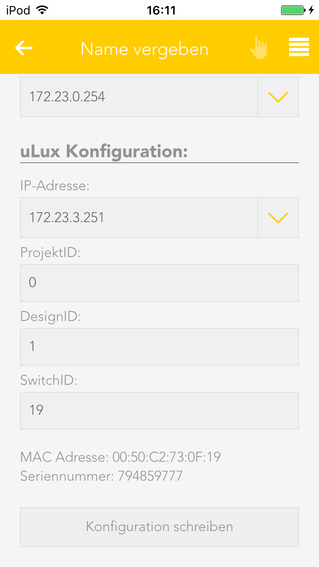
uLux configuration
This settings are automatically generated and don't need to be changed.
If you edit this settings, you will have to press the button 'write configuration' to transfer them to your uLux switch. The switch will then restart and boot up with your new configuration after some seconds.