Before Installing
This section provides all the necessary information for installing the Smart Building Automation system.

This section provides all the necessary information for installing the Smart Building Automation system.
A few basic points should be considered when planning a Smart Building Automation project. These can either be determined in advance or planned together with a Smart Building Automation partner.
The building plans provide the basis for the planning process. For each floor and room, consider the following:
In principle, the type of switch can be selected freely. However, the Smart Building Automation system uses pushbuttons for control. Pushbuttons with at least 2 to 4 pushbutton functions per unit (corresponding to one flush-mounted box) are recommended.
Since only 24 V signals are switched via the pushbuttons and sensors, there are no special requirements regarding their current-carrying capacity.
Example:
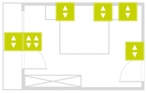
The following pushbuttons are planned for the bedroom:
When planning the lighting, consider the number, function, and type of lights to be used. It is recommended to mark the individual lighting circuits on a floor plan and specify whether each circuit should be switchable or dimmable. The type and number of lights in each circuit determine which modules are required.
For dimmable lighting circuits, the Schrack Smart Building Automation Dimming Module "L1424" is used. Each module can control two lighting circuits. An appropriate external dimmer is also required for each dimmable lighting circuit, depending on the type of light source, for example an Eltako SUD12 1-10 V universal dimmer. The Dimming Module "L1424" controls the external dimmer via 0-10 V or 1-10 V. The digital output of the module can be used to switch the external dimmer or an intermediate relay on and off.
For switchable lighting circuits, either the Schrack Smart Building Automation Light Module "L1244" with integrated 230 V/16 A relays or the Light Module "L1144" for connecting external relays can be used, depending on the application and load. Each module can control four lighting circuits.
Example:
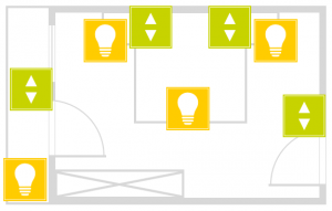
Two normal and two dimmable lighting circuits are planned for the bedroom.
The two normal lighting circuits are used for the ceiling and balcony lighting. A Schrack Smart Building Automation Light Module "L1244" with integrated 16 A relays is used for this purpose. Two of the four outputs are used, leaving the remaining two outputs available for other lighting circuits.
The two dimmable lighting circuits are used for the reading lights on the left and right sides of the bed. A Schrack Smart Building Automation Dimming Module "L1424" is used for these circuits. An appropriate external dimmer is additionally required for each lighting circuit.
The number and type of shading elements to be controlled determine which module is required. Whether the shading element is a roller shutter, internal blind, external blind, or awning is not relevant; the type of drive is what determines the required module.
The Schrack Smart Building Automation Blind Module "B1144" is used if the motor has separate lines for UP and DOWN and is supplied with 230 V. If the motor has a reversing switch, the Blind Module "B1244" is used.
Each of these modules can control two shading elements.
Example:
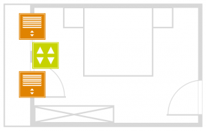
The bedroom has a window and a balcony door with shading elements that are to be controlled. Both shading elements are equipped with a standard motor (UP/DOWN, 230 V).
A Schrack Smart Building Automation Blind Module "B1144" is therefore used. The first output is used for the balcony door and the second output for the window.
The Schrack Smart Building Automation Room Climate Modules "C1144" and "C1244" are used for temperature control.
Four control valves and four Room Control Units can be connected to each Room Climate Module "C1144" or "C1244", corresponding to four separate room control zones.
Multiple valve actuators can generally be operated in parallel on each output. The number is limited by the load capacity of the relay output. This is particularly useful when several heating circuits are required in one room due to the heating pipe length, while the room is controlled as a single zone.
For the Room Climate Module "C1144", additional temperature sensors are required in the rooms to ensure correct temperature control. Temperature sensors are integrated into the Room Control Units "C1101", "C1102", "C1103", and "C1104". Depending on the model and configuration, these Room Control Units also provide functions such as setpoint adjustment, mode selection (comfort, energy-saving, frost protection), and a presence button.
Unlike the Room Climate Module "C1144", the temperature setpoint and mode cannot be changed directly via a Room Control Unit when using the "C1244". These settings can only be changed via the app, as only a PT1000 temperature sensor can be connected to the corresponding input of the "C1244".
Example:
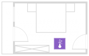
The room climate in the bedroom is to be controlled. The bedroom has one heating circuit.
A Room Control Unit "C1103" is used, providing a temperature sensor, setpoint adjustment, mode selection, and a presence button.
A Schrack Smart Building Automation Room Climate Module "C1144" is used for the heating circuit. One output is used for the valve actuator, leaving the remaining three outputs available.
Special functions such as doorbells, door openers, window contacts, garden irrigation, and scene pushbuttons require digital modules. To determine the number of modules required, first consider the number and type of special functions to be implemented.
The Schrack Smart Building Automation digital module "D1180" provides 8 digital inputs and is typically used in combination with the digital module "D1208", which provides 8 digital outputs. The digital module "D1344" combines 4 digital inputs and 4 digital outputs in a single module.
The inputs of all modules are designed for 24 V DC. Never connect higher voltages or AC voltage sources to the inputs, as this may cause irreparable damage to the module.
Depending on the wiring, the outputs can be used to switch either 24 V DC or 230 V AC. When switching 230 V loads, note that the load must be resistive and must not exceed 5 A. Conventional incandescent lamps are an example of a resistive load. LED lamps are capacitive loads and must be switched using an external relay. If in doubt, consult a qualified electrician or Smart Building Automation partner.
Example:
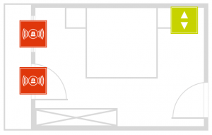
In the bedroom example, an alarm system is planned. Digital inputs are required for a pushbutton to activate and deactivate the alarm system as well as for the closing contacts of the window and balcony door.
A Schrack Smart Building Automation digital module "D1180" with 8 digital inputs is used. Four inputs are assigned to the bedroom: two for the closing contacts and two for the pushbutton. The remaining four inputs are available for other functions or rooms.
This example illustrates the planning of special functions using digital modules.
All cables must be routed to the distribution board in which the corresponding module is installed.
Each pushbutton requires a 24 V power supply (+24 V) and a wire connecting the pushbutton to the corresponding module input. For sensors such as pushbuttons, contacts, and room control units, the use of communication cables (F-YAY) or CAT5 cables is recommended.
If multiple pushbuttons are connected to the same module input, the wiring can either be daisy-chained in the room from one pushbutton to the next, with the connection made in the junction box, or each pushbutton can be wired individually to the distribution board and connected there. The second option centralizes the connection work in the distribution board, but requires more cabling during installation and additional space in the distribution board.
Use deeper junction boxes or boxes with additional space. This provides more room for wiring and makes connecting the cables easier.
Unlike in a conventional electrical installation, the pushbuttons do not come into contact with the 230 V mains supply. However, the 230 V mains supply must still be routed to the distribution board and connected to the Smart Building Automation modules to supply the connected loads, such as lighting circuits and blinds.
Remember to provide cables for components such as room control units, doorbells, window contacts, and door openers. Providing an additional cable during installation is preferable to having a cable missing later.
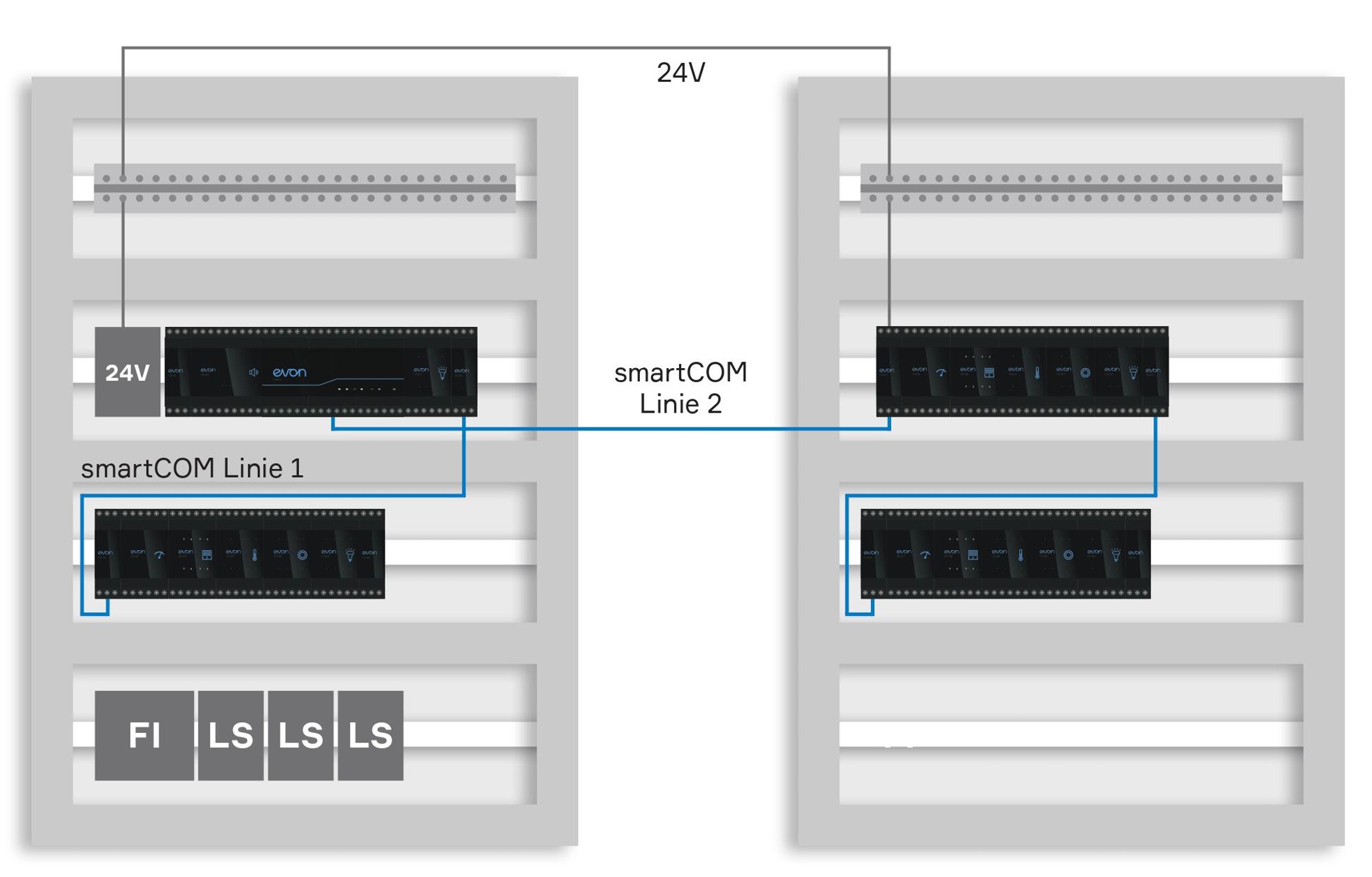
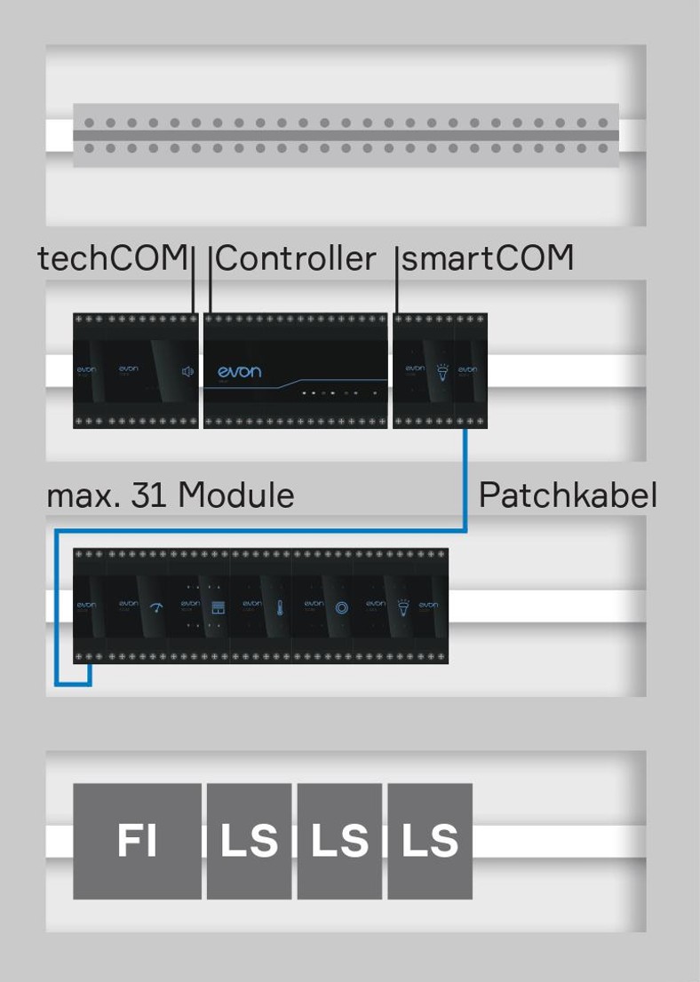
Sobald die Anzahl der Smart Building Automation Module, Relais und Taster sowie die Aufteilung auf die Verteiler festgelegt ist, können die Schaltschränke dimensioniert werden. Aufgrund der Standardhutschienenmontage mit 45 mm Blende können Smart Building Automation Module in jedem Standardverteiler installiert werden.
Alle Lichter, Jalousien und sonstigen Lasten sowie alle Schalter, Fensterkontakte und Sensoren werden in den jeweiligen Verteiler geführt. Für die Schalter wird die Verwendung von mehradrigen Fernmeldekabeln (F-YAY) empfohlen. Für eine übersichtliche Verdrahtung können diese auf LSA-Plus-Leisten aufgelegt werden (siehe Vorlage Rangierliste).
Es ist darauf zu achten, ausreichend Platz für das Netzteil, Bus-Umsetzermodule und den Busabschluss einzuplanen. Nach der Installation sollten im Schaltschrank noch etwa 20 % bis 30 % Platz für mögliche Erweiterungen frei bleiben.
Je nach Platzbedarf und den räumlichen Gegebenheiten kann die gesamte Steuerung in einem zentralen Schaltschrank untergebracht oder auf mehrere Subverteiler aufgeteilt werden.
Der Einsatz von Subverteilern reduziert die benötigten Kabellängen und damit den Verkabelungsaufwand. Zusätzlich wird das Einziehen der Kabel erleichtert.
Für jeden Subverteiler ist ein Bus-Umsetzermodul „S1200“ erforderlich, über das die Module des Smart Building Automation Systems miteinander verbunden werden. Das Bus-Umsetzermodul wird auch bei einem Zeilenumbruch benötigt, also wenn innerhalb eines Schaltschranks eine neue Zeile begonnen wird.