Planning
A few basic points should be considered when planning a Smart Building Automation project. These can either be determined in advance or planned together with a Smart Building Automation partner.
The building plans provide the basis for the planning process. For each floor and room, consider the following:
- Where will the distribution board be located?
- How many electrically operated shading elements are required, and which type of drive is used (standard or 24 V with reversing switch)?
- How many separately switchable or dimmable lighting circuits are required, and how are they to be controlled (external load relay, integrated load relay, dimming, or DALI)?
- How many room climate zones are required for temperature control? The number of heating circuits within each room climate zone is not relevant at this stage.
- Which special functions require inputs or outputs (e.g. doorbell, signal light, window contacts, presence sensors, cameras, audio, etc.)?
Switches
In principle, the type of switch can be selected freely. However, the Smart Building Automation system uses pushbuttons for control. Pushbuttons with at least 2 to 4 pushbutton functions per unit (corresponding to one flush-mounted box) are recommended.
Since only 24 V signals are switched via the pushbuttons and sensors, there are no special requirements regarding their current-carrying capacity.
Example:
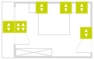
The following pushbuttons are planned for the bedroom:
- 1x 2-way pushbutton at the entrance for the ceiling light. A double-click switches off the dimmable reading lights and the ceiling light.
- 1x 4-way pushbutton and 1x 2-way pushbutton next to the balcony door. Two pushbuttons are used for UP/DOWN control of each of the two shading elements, one for the outdoor light, and one for the ceiling light.
- 2x 2-way pushbuttons, one on each side of the bed. One pushbutton is used for the dimmable reading light and one for the ceiling light.
- 1x 2-way pushbutton behind the bed for special functions. These functions could normally also be implemented using a double-click or long press. In this example, the additional pushbutton is included to demonstrate the use of the Schrack Smart Building Automation Digital Module "D1180".
Light Circuit
When planning the lighting, consider the number, function, and type of lights to be used. It is recommended to mark the individual lighting circuits on a floor plan and specify whether each circuit should be switchable or dimmable. The type and number of lights in each circuit determine which modules are required.
For dimmable lighting circuits, the Schrack Smart Building Automation Dimming Module "L1424" is used. Each module can control two lighting circuits. An appropriate external dimmer is also required for each dimmable lighting circuit, depending on the type of light source, for example an Eltako SUD12 1-10 V universal dimmer. The Dimming Module "L1424" controls the external dimmer via 0-10 V or 1-10 V. The digital output of the module can be used to switch the external dimmer or an intermediate relay on and off.
For switchable lighting circuits, either the Schrack Smart Building Automation Light Module "L1244" with integrated 230 V/16 A relays or the Light Module "L1144" for connecting external relays can be used, depending on the application and load. Each module can control four lighting circuits.
Example:
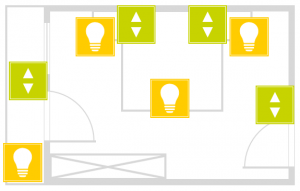
Two normal and two dimmable lighting circuits are planned for the bedroom.
The two normal lighting circuits are used for the ceiling and balcony lighting. A Schrack Smart Building Automation Light Module "L1244" with integrated 16 A relays is used for this purpose. Two of the four outputs are used, leaving the remaining two outputs available for other lighting circuits.
The two dimmable lighting circuits are used for the reading lights on the left and right sides of the bed. A Schrack Smart Building Automation Dimming Module "L1424" is used for these circuits. An appropriate external dimmer is additionally required for each lighting circuit.
Blinds
The number and type of shading elements to be controlled determine which module is required. Whether the shading element is a roller shutter, internal blind, external blind, or awning is not relevant; the type of drive is what determines the required module.
The Schrack Smart Building Automation Blind Module "B1144" is used if the motor has separate lines for UP and DOWN and is supplied with 230 V. If the motor has a reversing switch, the Blind Module "B1244" is used.
Each of these modules can control two shading elements.
Example:
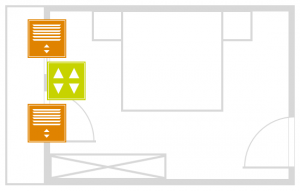
The bedroom has a window and a balcony door with shading elements that are to be controlled. Both shading elements are equipped with a standard motor (UP/DOWN, 230 V).
A Schrack Smart Building Automation Blind Module "B1144" is therefore used. The first output is used for the balcony door and the second output for the window.
Temperature Control
The Schrack Smart Building Automation Room Climate Modules "C1144" and "C1244" are used for temperature control.
- The Room Climate Module "C1144" is controlled via Room Control Units.
- The Room Climate Module "C1244" is controlled via PT1000 sensors or an external actual value (e.g. from an analog input).
Four control valves and four Room Control Units can be connected to each Room Climate Module "C1144" or "C1244", corresponding to four separate room control zones.
Multiple valve actuators can generally be operated in parallel on each output. The number is limited by the load capacity of the relay output. This is particularly useful when several heating circuits are required in one room due to the heating pipe length, while the room is controlled as a single zone.
For the Room Climate Module "C1144", additional temperature sensors are required in the rooms to ensure correct temperature control. Temperature sensors are integrated into the Room Control Units "C1101", "C1102", "C1103", and "C1104". Depending on the model and configuration, these Room Control Units also provide functions such as setpoint adjustment, mode selection (comfort, energy-saving, frost protection), and a presence button.
Unlike the Room Climate Module "C1144", the temperature setpoint and mode cannot be changed directly via a Room Control Unit when using the "C1244". These settings can only be changed via the app, as only a PT1000 temperature sensor can be connected to the corresponding input of the "C1244".
Example:
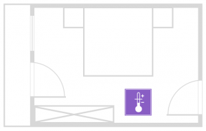
The room climate in the bedroom is to be controlled. The bedroom has one heating circuit.
A Room Control Unit "C1103" is used, providing a temperature sensor, setpoint adjustment, mode selection, and a presence button.
A Schrack Smart Building Automation Room Climate Module "C1144" is used for the heating circuit. One output is used for the valve actuator, leaving the remaining three outputs available.
Special Functions
Special functions such as doorbells, door openers, window contacts, garden irrigation, and scene pushbuttons require digital modules. To determine the number of modules required, first consider the number and type of special functions to be implemented.
The Schrack Smart Building Automation digital module "D1180" provides 8 digital inputs and is typically used in combination with the digital module "D1208", which provides 8 digital outputs. The digital module "D1344" combines 4 digital inputs and 4 digital outputs in a single module.
The inputs of all modules are designed for 24 V DC. Never connect higher voltages or AC voltage sources to the inputs, as this may cause irreparable damage to the module.
Depending on the wiring, the outputs can be used to switch either 24 V DC or 230 V AC. When switching 230 V loads, note that the load must be resistive and must not exceed 5 A. Conventional incandescent lamps are an example of a resistive load. LED lamps are capacitive loads and must be switched using an external relay. If in doubt, consult a qualified electrician or Smart Building Automation partner.
Example:
In the bedroom example, an alarm system is planned. Digital inputs are required for a pushbutton to activate and deactivate the alarm system as well as for the closing contacts of the window and balcony door.
A Schrack Smart Building Automation digital module "D1180" with 8 digital inputs is used. Four inputs are assigned to the bedroom: two for the closing contacts and two for the pushbutton. The remaining four inputs are available for other functions or rooms.
This example illustrates the planning of special functions using digital modules.