Extended Features
If the steps so far are not sufficient, you can adapt your evonHOME with further functions.
If the steps so far are not sufficient, you can adapt your evonHOME with further functions.
Nachdem der Fingerscanner an das passende "evonHOME Auxiliary – RS485" Modul angeschlossen wurde, kannst Du diesen im evonHOME System hinzufügen.
Lege dazu ein neues Zutrittssystem über den entsprechenden Button an.
Im nun erscheinenden Popup werden alle erkannten Zutrittssysteme gelistet. Du kannst das gewünschte System über einen Klick auf den Namen oder das Plus Symbol hinzufügen.
Wenn Du mehrere Zutrittssysteme besitzt, kannst Du den zweiten Button benutzen um die LEDs des verlinkten Systems aufblinken zu lassen und es dadurch identifizieren.
Wurde ein System ausgewählt, kannst Du diesem im zweiten Schritt einen Namen geben.
Hast Du Deine Eingabe bestätigt, wird das Zutrittssystem erstellt und Du kannst mit der Konfiguration beginnen.
Klicke zur Konfiguration deines Fingerscanners einmal auf das neue erstellte Zutrittsystem und navigiere zu den Einstellungen in das ParameterPanel.
Im Bereich "Status" werden Dir Informationen über die Verbindung zu deinem Zutrittssystem angezeigt.
Wenn Du mehrere Zutrittssysteme besitzt, kannst Du den Button "Identifizieren" benutzen um die LEDs des verlinkten Systems aufblinken zu lassen und es dadurch zu finden.
Nun kannst Du damit beginnen Nutzer anzulegen, für die Du anschließend Finger oder RFID Chips einlernen kannst.
Klicke hierzu auf das Plus Symbol.
Du wirst nun durch die einzelnen Schritte geleitet, die für das Anlegen eines Benutzers und dem Einlernvorgang notwendig sind.
Wähle zuerst den evonHOME Benutzer aus für den Du Finger oder RFID Chips einlernen willst.
Als nächstes siehst du eine Übersicht der bereits eingelernten Finger/Chips. Klicke auf das Plus Symbol um weitere hinzuzufügen.
Wähle nun den gewünschten Finger oder RFID Chip aus und klicke auf "Einlernen".
Der Einlernvorgang wird nun gestartet und Dein Fingerscanner blinkt orange. Ziehe nun den betreffenden Finger mehrmals langsam über den Scanner, bis dieser blau leuchtet. Der Finger wurde nun erfolgreich eingelernt.
Du kannst nun weitere Finger oder einen RFID Chip einlernen. Sobald Du fertig bist klicke auf "weiter".
Wenn Du eine Tür mit Türöffner besitzt kannst du diese im nächsten Schritt mit Deinem ausgewählten Benutzer verknüpfen. Dadurch wird die Tür entsperrt, sobald der Finger oder RFID Chip des Benutzers erkannt wird.
Sobald Du auf "Weiter" klickst, ist die Konfiguration abgeschlossen und Du kannst Deine Änderungen über einen Klick auf "Fertig" bestätigen. Alternativ kannst Du auch ein paar Schritte zurück gehen und noch weitere Finger/RFID Chips hinzufügen.
Alle erstellten Benutzer erscheinen nun in der Liste des Zutrittsystems. Neben jedem befindet sich ein kleines Schloss, über das der betreffende Benutzer gesperrt werden kann, wodurch er keine Zutrittsberechtigung mehr hat.
Außerdem können Benutzer über das X-Symbol gelöscht oder bei Klick auf den Namen angepasst werden.
Falls Du später weitere Finger/RFID Chips zu einem bereits angelegten Benutzer hinzufügen möchtest, musst Du nur auf den betreffenden Namen in der Liste klicken.
In der sich öffnenden Ansicht siehst Du nun alle bisher eingelernten Finger/RFID Chips, kannst diese löschen oder (über das Tür-Symbol) für den Türöffner deaktivieren. Außerdem kannst Du verknüpfte Türen zu diesem Benutzer hinzufügen und entfernen.
Dein Zutrittssystem steht Dir auch bei der Erstellung von Szenen zur Verfügung. Da viele Funktionen jedoch an einen Nutzer gekoppelt sind, findest du alle Auslöser, die einen bestimmen Nutzer betreffen unter "Benutzer".
Beispiel:
Wenn Du eine Szene erstellen willst, die ausgelöst wird, sobald irgendein beliebiger Finger erkannt wird, findest Du die betreffenden Funktionen unter "Wenn"-"Apps"-"Zutrittssystem".
Möchtest Du eine Szene auslösen, wenn ein bestimmter Benutzer oder damit verknüpfter Finger erkannt wird, befinden sich diese Auslöser unter "Wenn"-"System"-"Benutzer".
The app “alarm system” lets you create a personal alarm system for your evonHOME. The alarm system is divided into a central alarm system and one or more alarm groups. Alarm groups divide the alarm system into several areas.
The app “alarm system” is located under “all apps” – “alarm system”.
The initial password for the Alarm System is set to "1234".
It is highly recommended to change it on initial setup. You can find the related options in the SettingsPanel (See section configuration).
If the alarm system or one or more alarm groups have been activated, the defined activation delay for each alarm group must first expire before the alarm can be triggered. Once the activation delay has expired, if a movement detector is triggered then a trigger delay is activated. During this time, the alarm system can be de-activated without an alarm being triggered. Once the trigger delay has expired, the silent alarm is triggered and a notification is sent. Once the silent alarm time has expired, the actual alarm is triggered and a further notification is sent and the outputs linked to the alarm system are switched.
Activation time is necessary for the following situation: you want to leave the house and activate the alarm before you go. To make sure that you do not inadvertently trigger the alarm yourself, you need the activation delay.
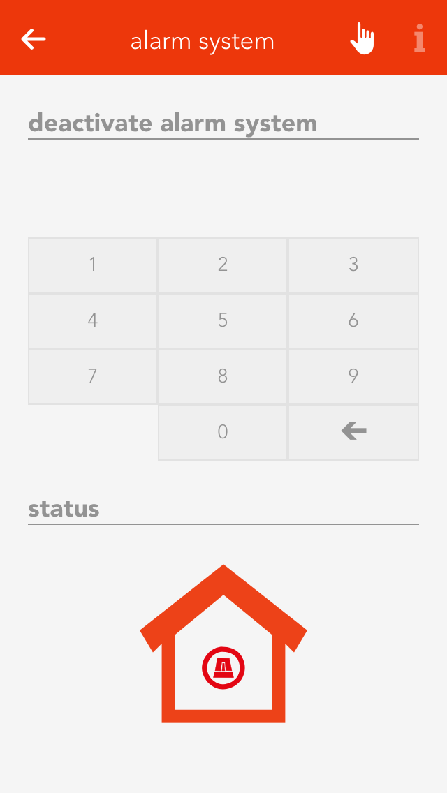
If you want to activate the alarm system, you can either do this via the app by opening the alarm system (“all apps” –“alarm system”) and select the button “activate” in the operator panel for the alarm system, or you define a button to activate the alarm and you use this button (how you do this is described in the chapter configuration). Deactivating the alarm is done the same way via the app, only that you have to enter a password. Deactivation via a button works identically to activation.
You can also find a history of past events in the OperatorPanel of the alarm system which gives you detailed records about the dates and times when it got triggered, activated or deactivated.
Warning, since the alarm system can be deactivated without a password using a button, you need to select a button that is not immediately visible!
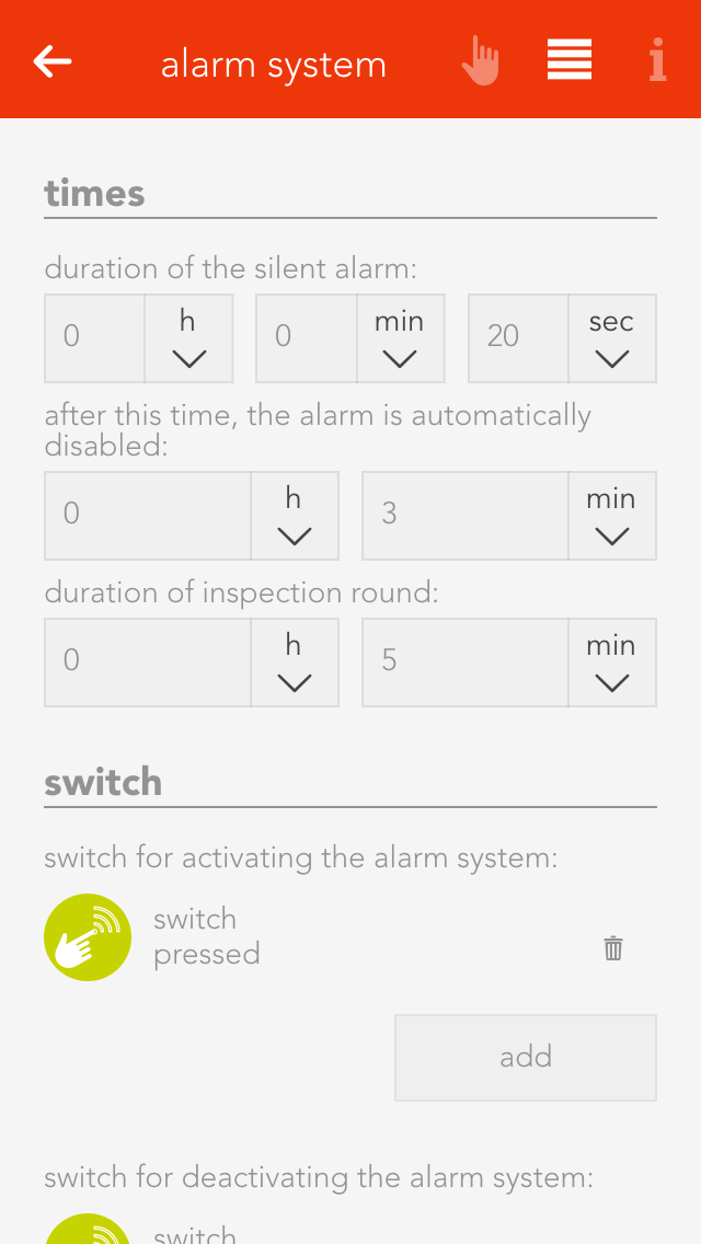
Duration of silent alarm
Enter the time for silent alarm here.
Automatically deactivate alarm after
Automatically deactivates the alarm after expiration of this time. This is important if you are holiday and something triggers the alarm. If this option was not available, the alarm would never switch off and your neighbours would not be too pleased with you.
Duration of patrol
This is the time the alarm should be deactivated for while you make a patrol.
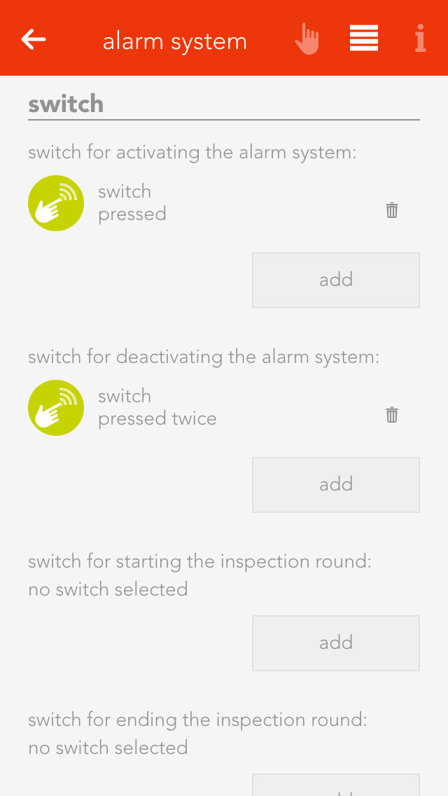
Button to activate the alarm system
Select a button to activate the alarm system.
Button to deactivate the alarm system
Use the button “add” to select a button to deactivate the alarm system. Warning! This button can deactivate the alarm system without a password. Consider the use of such a button carefully.
Button to start patrol
Select a button to let you start a patrol.
Button to end patrol
Select a button to tell the system you have completed your patrol.
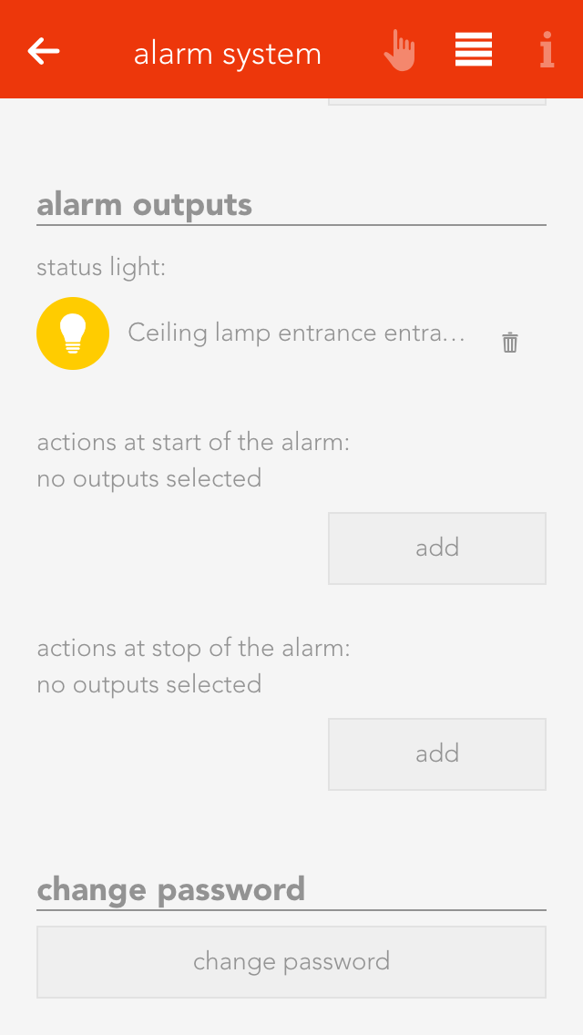
Status light
Select a light that will flash twice when the alarm system has been activated and once when deactivated.
Actions when alarm triggers
Use the button “add” to select all the actions you wish to happen when an alarm is triggered (e.g. switch lights on, activate siren, etc.).
Actions when alarm stops
Select what should happen when the alarm is deactivated. Caution! Do not forget to deactivate the actions started when the alarm was triggered.
Change password
Change the password to deactivate your alarm system.
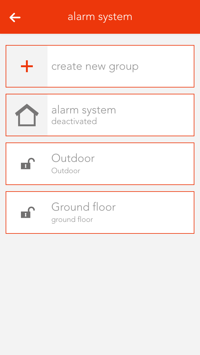
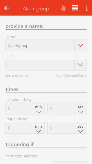
An "Alarm Group" represents a section of your alarm system which you want to secure. You can create an unlimited number of groups and use them to arrange your house into various segments. This makes it possible to create different settings for each group and only activate the ones you need.
You can, for example, create a new alarm group for each floor and by using a scene, only secure the ones which are not occupied at the moment.
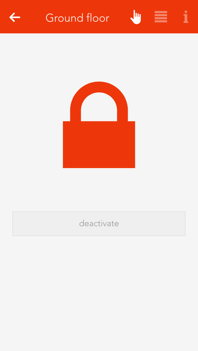
The OperatorPanel shows you the current state of the group. If the lock is closed, the group is currently active and will be taken into account when you activate the alarm system.
To change the state of the group, you can click on the small lock in the ObjectPanel of the group or use the button in the OperatorPanel.
Be aware that once the alarm system is activated, you can not change the state of each alarm group. If you want to activate or deactivate a group, you will have to deactivate the alarm system first.
Activation delay
If the alarm system and this group have been activated, then the alarm in this group can only be triggered after this time has expired. (Important if you wish to leave the house without triggering an alarm yourself).
Trigger delay
The silent alarm is triggered after this time has expired.
Trigger if
Select all the triggers that you wish to be able to set off this alarm.
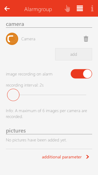
camera
Select one or more cameras which will capture up to 6 images if the alarm goes off. You can change the interval for the captured images by using the provided slider. For example: If you set the interval to 2 seconds, each camera will try to capture an image every 2 seconds until 6 images are recorded. You can view the captured images in the "pictures" section below this setting.
Test alarm
The button “test alarm” lets you trigger an alarm in this group. The group and the central alarm system are activated, the panel is closed and an alarm is triggered. Use this to test your alarm system.
“Bathroom heating” lets you configure suitable heating systems and control their times.
These functions are located under “all apps” – “bathroom heating”.
To add a new bathroom heater, click on the element “add”. First allocate a name to your bathroom heater in the parameter panel, then you can continue with the configuration (described below).
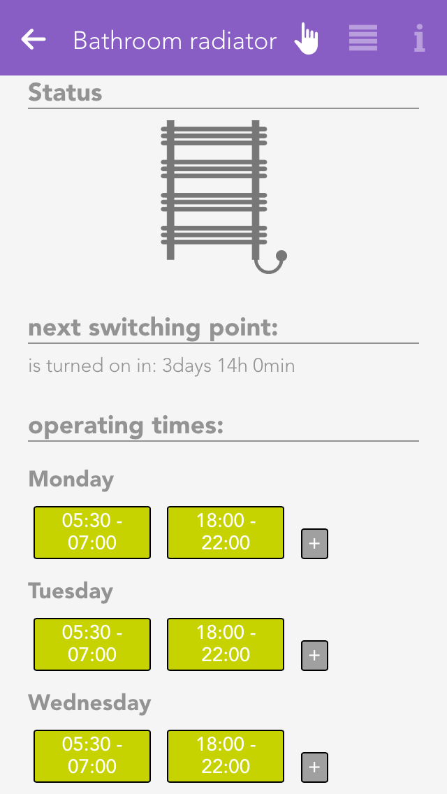
You can determine what time each of your bathroom heaters should be on. You do this by defining the operating times in the operator panel. You can define one or more time intervals where your heater should heat for each weekday.
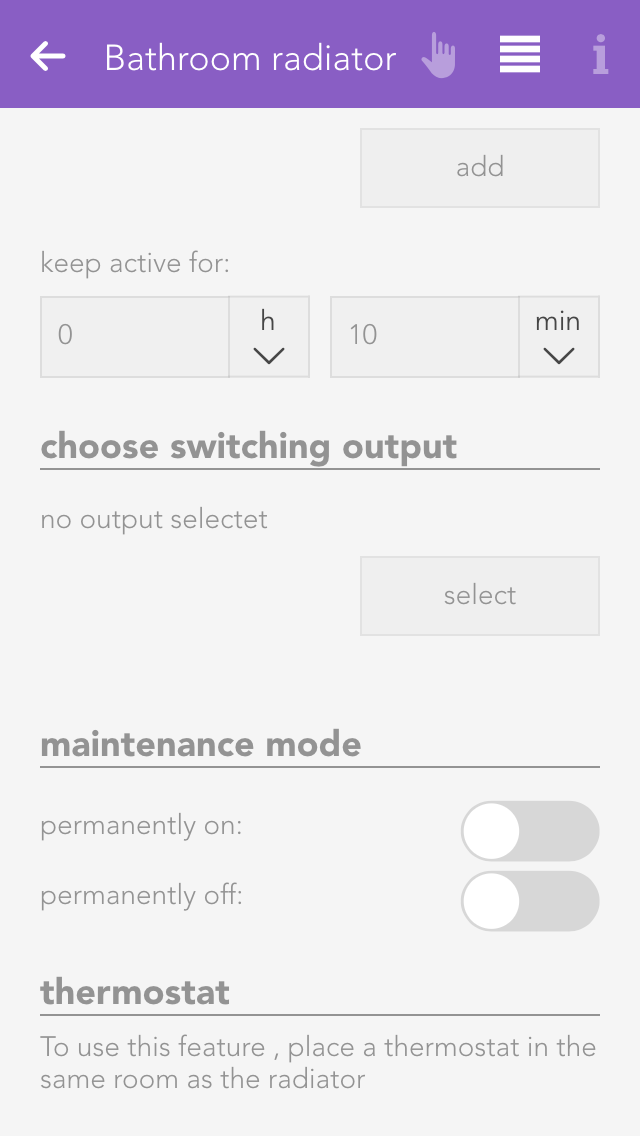
Apart from the operating times, you can also define a button to activate each bathroom heater, where it is connected and whether it should be switched into maintenance mode.
Additional trigger
Select the trigger and the duration for which the bathroom heater should additionally be activated for a short period of time.
Select socket
This lets you define which socket your bathroom heater is connected to.
Maintenance mode
This lets you permanently switch the maintenance mode for the bathroom heater on or off.
The app “Camera” lets you integrate your evonCAM into your system.
The Camera app is located under “all apps” – “Camera”.
In order to create a camera, click on the box “add new evonCAM” inside the app.
All found evonCams including a preview image will now be listed in the popup which appears. Once your camera shows up on this list you can select it and it will be added to your system and is ready to be used.
If your camera ist not immediately found in your network, you have the option to restart the search or to configure it yourself. In this case a camera will be added for which you have to add the required settings (IP address, username, password).
To correctly configure the camera, enter the IP address of the camera into your browser.
If you followed the steps to integrate your evonCAM and the camera was found and added to your system, no further configuration is required.
In case you chose the manual configuration (e.g. because the camera was not automatically found in your network), you can change or adapt the required settings at any time in the ParameterPanel of the camera.
This can also be necessary, when you make changes to the standard username/password or the IP address.
If you change the settings (username/password) of the camera (via its webinterface) the app or browser may ask you to enter the new credentials.
After you did this, it is important to go to the ParameterPanel of the camera and update those settings there, otherwise you will regularly be asked to enter the new credentials.
You can also change the IP of your camera to a specific static address. Changing settings here will write the new network configuration to the camera which will then restart with the new settings applied.
If you change the IP address, other required network settings (gateway and subnetmask) will automatically be taken from the current evonHOME controller network configuration. If you want more control over this settings there is also an extended form available under the additional parameter button.
The camera panel supports two different sizes. If you hold down your finger (cursor+left mouse button) on the panel for some seconds a bar will appear on the bottom of your screen, which gives you the ability to change the size from small to large.
The large size supports displaying the current camera video inside the panel. Like most other panels, you can add this to your favorites on the start screen which will allow you to always see the current camera image.
With the icon located on the top right corner of the camera image, you can open a popup with bigger view of the video stream, which is well suited for bigger screen sizes like tablets.
The camera OperatorPanel displays the current video/image if the correct credentials are added in the settings. You can also open a popup containing a bigger sized version of the camera image by clicking the icon in the top right corner of the image.
If you did not enter a name for the camera yet, the associated input field will also appear here.
“Circulation pump” lets you configure and control the times for suitable pump systems.
These functions are located under “all apps” – “circulation pump”.
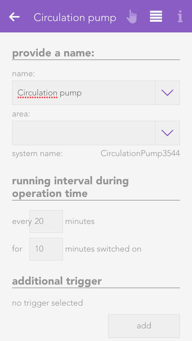
To add a new circulation pump, click on the element “add circulation pump”. The next step is to allocate a name for your circulation pump in the parameter panel. Then you can continue with the configuration (described below).
You can define the operation times for each one of your circulation pumps. This is done by defining the operating times in the operator panel. You can define one or more time intervals for each weekday when you wish the circulation pump to be in operation.
In addition to the operating times, you can also define intervals within the operating times, which trigger activates them, where they are connected and whether they should be put into maintenance mode.
Active interval during operating time
Define the intervals within the operating time you wish to circulation pump to be active.
Additional trigger
Select the trigger and the duration for which the circulation pump should be additional active for a short period of time.
Select socket
Define which socket the circulation pump is connected to.
Maintenance
Switch the circulation pump permanently on or off for maintenance purposes.
The clock lets you create an alarm clock, a timer or a weekly programme. The next chapters explain how to use them.
The clock is located under “all apps” – “clock”.
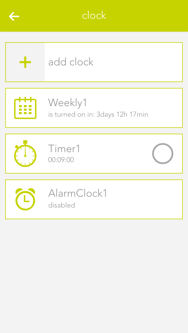
To create an alarm clock, a timer or a weekly programme, simply open the app “clock” and select “add clock”. A window then opens offering you a selection of elements you can create.
The app “alarm clock” lets you create an alarm clock that goes off at the time you define and is shut off after a certain time. An alarm clock is intended to be used with a scene to react to the alarm and the end of the alarm.
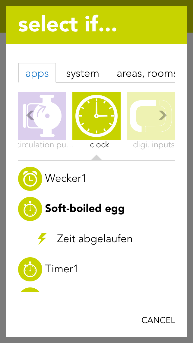
In order to use this alarm with a scene, it must first be named and then you can click on “add” in the scene’s “IF” and select the app “Clock”, unfold the alarm clock and select either “alarm triggered” or “alarm ended”.
To define the alarm time, simply click on the currently defined time and select the time you wish for the alarm. You must also activate this alarm via the option “activate”.
The item “repeat” lets you select which on weekdays should the alarm be repeated. If you only want the alarm to go off once, select the option “just once”.
The length of time the alarm is active can be set under “extended” by activating the option “activate extended settings”. You will need the active alarm time if you want the alarm to last for a specific time. For example, if you have activated the alarm for 8pm with an active time of 10 minutes, then the alarm is active from 8 pm till 8:10 pm and then switches itself off. If you haven’t activated this option then the alarm stops directly after the trigger.
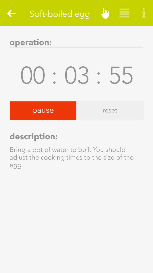
The app “timer” lets you define a countdown that, once the defined time has expired, can invoke a scene. You can also allocate a signal light to this timer that signals when the time has expired.
To adjust the time, click on the currently defined timer for this timer in the operator panel under “operation” and change it as you require.
The button “start” is used to start the timer and “reset” to reset the start time. The button “pause” stops the timer and you can continue the timer by pressing “start”.
In order to be able to use this timer with a scene, it must have a name. Then you can select the trigger “time expired” in the scene under “IF” and the appropriate action to be carried out when the timer has expired. You can also use the timer in the scene for the “THEN”. This lets you start, stop or reset a timer via a scene.
Once you have allocated this timer a name and optionally a room, you can begin with the configuration.
You can add as many lights as you want in the item “signal light” using the button “add”. These lights are intended to flash on and off and the number of flashes can be set via the option “number of flashes”. The duration of each flash can be set via the “duration of signal flash”.
The app “weekly program” lets you define up to 3 time periods per day in which you can execute actions. In order to be able to carry out an action, a scene must react to the activation and de-activation of the weekly program.
In order to be able to use this weekly program, you must give it a name. Once done, you can select the triggers “activated” and “de-activated” in the scene’s “IF” statement. For example, if a time from 9 am to 10 am has been defined for each Monday, then “activated” is invoked at 9 am and “de-activated” is invoked at 10 am. Furthermore you can use the weekly program in the scene for “THEN” by selecting “switch on once” (“switch on once” is explained in the chapter “configuration”).
To create an entry in the weekly program, click on “+” for the desired day. This opens a window where you can configure the entry. You have the following possibilities:
Day
The weekday for which this entry is to be created.
No end time
If you only want to define a start point then activate this option. If a point has no end time, then the weekly program is activated after the time for the “runtime for additional trigger” has expired (located in the parameter panel).
From
This is the start point for your entry
Until
This is the end point for your entry
To edit an entry, click on the previously created entry (in the operator panel) and then proceed the same as for creating the entry.
Runtime for additional trigger
If the weekly program is activated once via the additional trigger, then the weekly program remains active for the defined time. If you have an entry without end point, then the weekly program also remains active for this time after the defined time has expired.
Additional trigger
You can add as many additional triggers as you wish that trigger the weekly program once.
This app is used when you connect a counter to a digital input. With it's help you can react to the signals send form the counter unit and evaluate them. For example, you can record a power consumption in kW, set various value limits and react to them later in scenes.
The Counter ist located under “all apps” – “Counter”.
The minimum pulse length for a counter connected to a digital module is 100ms. For faster counters, please use the input located on the cpu module.
To use a counter in combination with the corresponding app, you will have to connect it to a digital input of your evonHOME (DI1 - DI4 on the CPU or 'evonHOME Digital 1180' or 'evonHOME Digital 1344'). Then follow these steps:
If you find not create a counter in your evonHOME system yet, you have to convert a digital input into one.
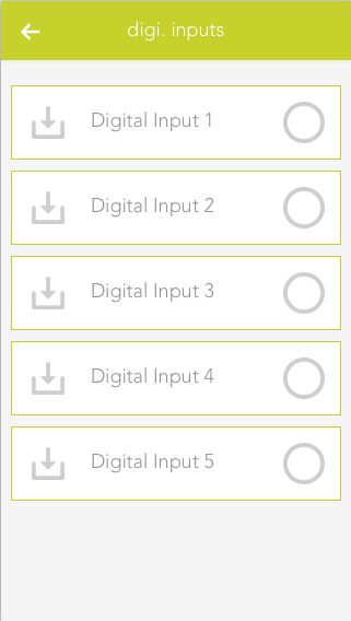
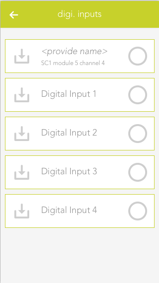
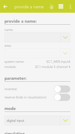
Navigate to te digital inputs in 'All Apps' - 'Digital Inputs', select the desired input and open the ParameterPanel.
In the settings for mode, choose 'Counter'. The digital input will now be converted into a Counter an will be listed in the Counter app.
Every Counter allow you to change certain settings, which determine what will be counted (e.g. kWh) and what limits exists.
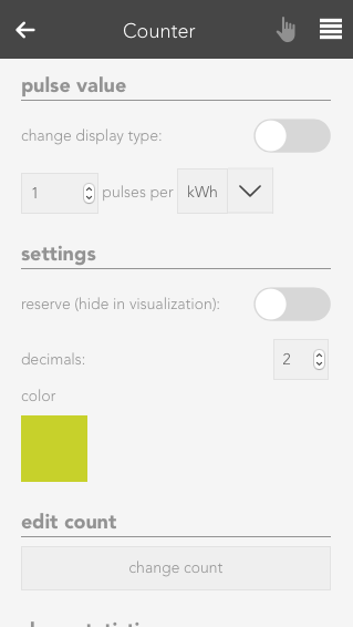
Pulse value
Choose the significance of the impulse which gets received by the counter. The necessary settings for this are usually listed on the counter device.
Settings
Inverted
If this option is activated, only falling edges will be counted instead of rising edges.
Reserve
Hides this counter from the visualization.
Color
Changes the color of the visible graphs.
Edit count
Here, you can set the current count to a desired value
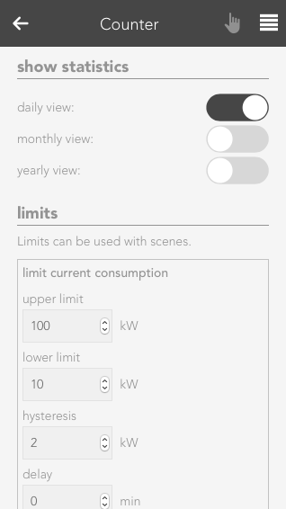
Show statistics
Choose the graph/chart, which will be displayed in the OperatorPanel.
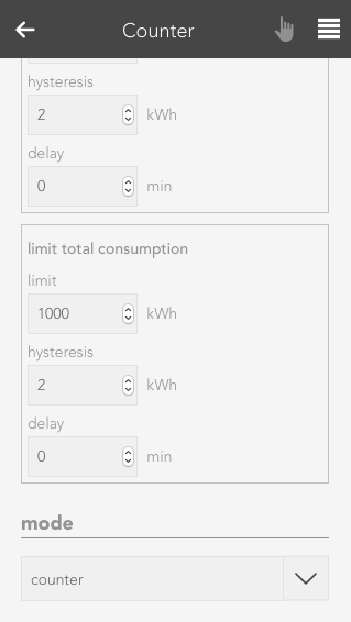
Limits
You can choose various limits (and according delays) here, which you can then link in scenes. Linkable values are: 'current consumption - upper limit', 'current consumption - lower limit' and 'daily consumption - limit'.
Mode
With this setting you can convert/revert a counter to a digital input or switch
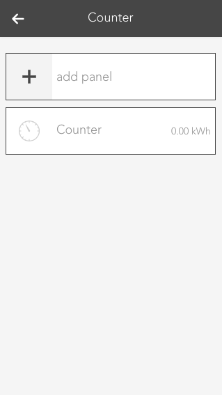
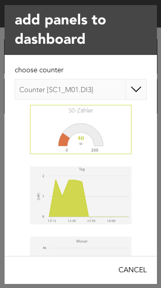
Once a Counter has been created, you can add additional visual panels. Those grant you an overview about the evaluated values.
To add such a panel, use the button "add panel".
In the popup which will appear, you can choose between several graphs/charts. To do so, you have to select the corresponding Counter under 'choose counter' and then one of the desired charts.
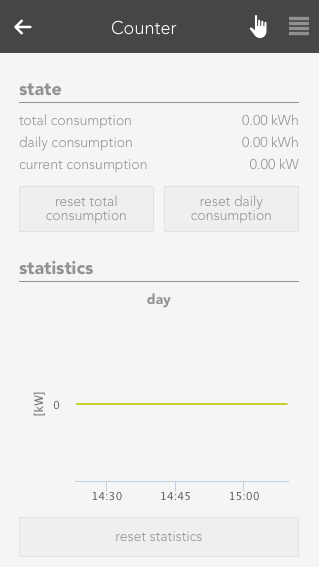
The OperatorPanel gives you an overview about the measured values. The following sections exist:
Status
Gives you information about the total, daily and current consumption. In addition, you can also reset the counter.
Statistic
The graphs/charts which you can activate in the ParamterPanel will be shown here. The statistics which are shown here can also be reset with the corresponding button.
This section contains information on using connected DENON devices.
Denon lets you play music throughout your house, whether from a USB stick, music server, Internet radio, iPod, AUX or online music.
The Denon app is located under “all apps” -“Denon”.
Currently, only the DENON DRA-N4 amplifier is supported by evonHOME.
Volume
You can change the volume via the “+” and “-“ buttons, or use the slider.
Source
Use this to determine where your music is to come from and see the Denon display below it. Navigate around your Denon using the 4 arrows and the enter button.
Favourites
Add the current programme to your favourites list using the button “add to favourites” so that you can find it again quickly. All your favourites are displayed in a list below this.
ON/OFF
Switch your Denon on an off.
Status
Shows which music source is currently active, Internet music, iPod etc. and shows the current IP address.
In the parameter panel, you can also define whether this Denon is to be switched with the universal scenes or not “remove from universal scene”) and how loud the Denon can be allowed to be.
You can link the Denon to a scene. You have several possibilities.
Use the following if the IF statement
Pause
The scene is invoked when the sound is paused.
Play
The scene is invoked when the music begins, i.e. when the play button has been pressed.
The “THEN” can have the following triggers:
Switch off
The Denon is switched off as soon as the scene is invoked.
Switch on
The Denon is switched on as soon as the scene is invoked.
PlayMusic
The Denon begins play music at the start volume which then increases to the define target volume. The ramp-up time defines how long it takes to reach the target volume. The favourite number lets you choose which favourite you wish to play.
The Detector app allows you to use a digital input for alarms/notifications. This can be useful in cases like when you want to connect a fire alarm to your evonHOME.
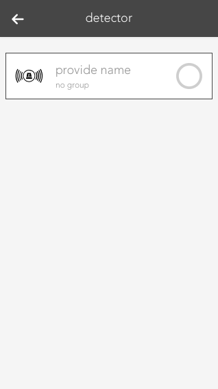
The Detector app is located under “all apps” – “Detector”.
To create a Detector, you will need a digital module ("evonHOME Digital 1180" or "evonHOME Digital 1344") with an digital input. Then, follow these steps:
Navigate to the app 'Digital Inputs', which you can find under 'All Apps'.
Select the desired digital input, which you want to use as a Detector.
Navigate to the settings of the chosen digital input and change its mode to 'Detector'.
The Digital Input changed into a Detector and can now be found in the 'Detector' app.
After you changed a Digital Input into a Detector, it will react to incoming signals and trigger an alarm, depending on its configuration.
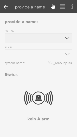
A detector will display if his input is currently active and if it is triggering an alarm.
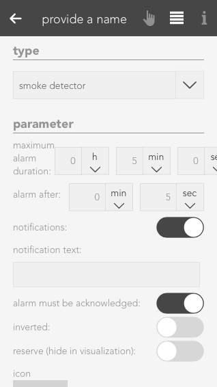
Each Detector allows you to configure the triggered alarms. Here you will find the description about all available options.
Type
This are pre configured settings for different use cases. Each one comes with a predefined notification text, settings and specific icon.
Alarm after
Defines the timespan for which a signal has to be active on the digital input to trigger an alarm.
Notification
Here you can choose to receive a notification once an alarm gets triggered.
Notification text
Set the text you want to see in the notification.
Alarm must be acknowledged
If this option is active, an active alarm has to be manually terminated instead of ending once the input signal stops.
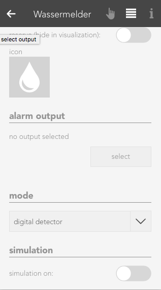
Reserve (hide in visualization)
Once active, the Detector will be hidden in the visualization.
Icon
Defines which image should be used for this Detector.
Alarm Output
You can choose a digital output, which will be triggered in case of an alarm, here.
Mode
Here, the Digital Input which is used for this Detector can be switched back to another mode.
Simulation on
Activates the simulation and allows you to set a value via the setting 'Simulation Value'. Attention: If the simulation is active, real values are ignored!
Simulation Value
Change the simulated value with this setting.
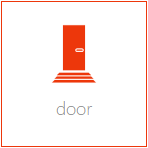
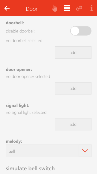
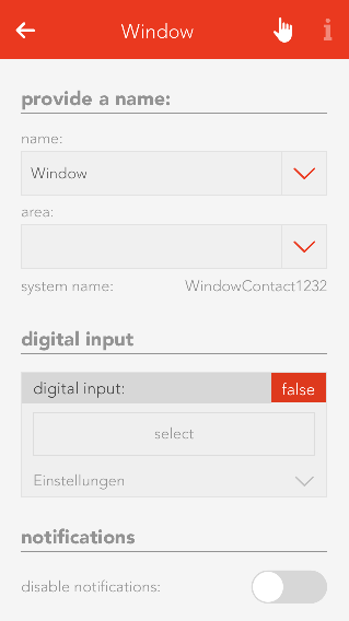
The app “door” lets you create a door for your evonHOME. You can link a camera, a bellring button, a bellring and a door opener contact to such a door.
The app “door” is located under “all apps” – “door”.
If you open the operator panel for your door, then you can see the camera image (if a camera is linked to this door) and a button “open door” that lets you open this door (if a door open contact has been selected).
As soon as someone rings the bell for this door, you will receive a notification and a photo is taken of the moment the bell was rung that you can see when you open the notification.
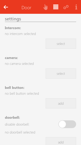
Intercom
Choose a connected intercom. "Camera" and "Bellpush" will automatically be assigned.
Camera
This field lets you select a camera for this door. The camera image is then always displayed on the operator panel.
Bellpush
Use the button “add” to add one or more buttons you wish to use to ring the doorbell.
Doorbell
Select the digital output that is connected with the doorbell.
Door opener
Select the digital output connected to the door opener using the button “add”.
Signal light
If you in a room where it is not possible to hear the doorbell, you can select a light in this room that will flash when someone rings the doorbell
Number of flashes
Define the number of times the signal light is to flash when someone rings the doorbell.
Signal light on time
Defines how long the signal flash is to be.
Door open time
Defines how long the door remains open, if you open it via the app.
Doorbell time
Defines how long the digital output for the doorbell is to remain active.
Melody
If you want a melody to play on your smartphone, or tablet etc. when someone rings the doorbell, then you can choose here between two melodies.
Simulate
You can simulate the doorbell button press using the button “ring” to test whether you have satisfactorily configured all options according to your requirements. This has the same effect as if someone had really pressed the doorbell.
If you want to be able to use the built in microphone and speaker of your intercom to talk to visitors, we recommended to download and use the following apps:
iOS - https://itunes.apple.com/at/app/mobotix/id527836206?mt=8
Android - https://play.google.com/store/apps/details?id=org.abionix.axviewer&hl=de
The "Fronius" app allows you to integrate your Fronius system into your evonHOME.
The Fronius app ist located under 'all apps' - 'Fronius'.
All limits, which can be configured in the Fronius app, can also be used as triggers for scenes.
To integrate your Fronius system, please follow the steps below.
(You will need the IP Adress of your PV-system for this)
Open the Fronius app an choose 'add'.
Enter the IP address of your PV system in the now appearing popup.
Confirm it with the button 'add'.
Once entered successfully, all installed elements of your PV system will be shown.
If you integrate a Fronius system, every installed element (which is supported by evonHOME) of your PV system will be displayed.
Additionally the Dashboard of the Fronius app can be extended with more panels.
Once a PV system is integrated, you can choose to add additional panels by using the 'add' button.
You can choose between 'My Fronius', an overview about the current energy flow in your system, "Efficiency" (of the inverter), “Energy“, "Supply" and "Phase Distribution".
There is also a dynamic diagram available, which can be customized by the user. It allows you to choose between different values and diagram types.
All panels can be added to the home screen by selecting them with a long click/press.
Operation
The most important values are displayed in the first part of the detail view (Operator Panel).
Additionally, the utilization and energy values for year, month and week will be shown in a diagram.
Configuration
The second part of the detail view (Parameter Panel) allows you to view detailed values and and adjust limits. Three power limits can be set which will trigger an event once exceeded or below the set value.
Detail values
Lists values which can be used by an inverter in the system.
Scenes
The inverter offers an event for the power limits 1,2 and 3 in case they are exceeded (above/below).
Operation
The operator panel of the Smart Meter displays the current feed-in/supply to or from the power grid and presents them in an area diagram.
Configuration
The parameter panel displays the phase distribution in a bar chart and allows you to adjust feed-in/supply limits for he power grid, which will throw an event once exceed (below/above). In addition, all detail values of the Smart Meter are displayed.
Detail values
Shows values which can be used by a Smart Meter in the system.
Scenes
The Smart Meter offers events for feed-in/supply to or from the power grid in case they are exceeded (above/below).
Operation
The operator panel displays the current charging/discharging rate (in watt) and the current battery power level.
Configuration
The parameter panel allows you to adjust the minimum charging level, which will trigger an event in case it is exceed (above/below), and to view the detail values of the battery.
Detail values
Shows values which can be used by a battery in the system.
Scenes
The battery offers events for exceeding (above/below) the minimum charging limit.
Die Anbindung und Steuerung einer Wärmepumpe an Dein evonHOME System erfolgt über digitale Eingänge und digitale oder analoge Ausgänge, je nachdem, was Deine Wärmepumpe unterstützt.
Wurde die Wärmepumpe an betreffende Ein- Ausgänge angeschlossen, muss sie in Deinem evonHOME System angelegt werden.
Wähle dazu "Wärmepumpe hinzufügen".
Nun wird eine neue Wärmepumpe erstellt und kann konfiguriert werden.
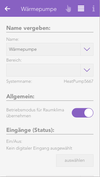
Nachdem Du eine neue Wärmepumpe in evonHOME angelegt hast, solltest Du dieser zunächst einen Namen geben und sie einem Raum zuordnen.
In den Einstellungen hast Du auch die Möglichkeit, die Funktion "Betriebsmodus für Raumklima übernehmen" zu aktivieren. Ist diese Funktion aktiv, wird bei Änderung des Betriebsmodus (Heizen/Kühlen) der Wärmepumpe auch der Modus des Raumklimas in den Einstellungen angepasst.
Um die angebundene Wärmepumpe zu steuern oder ihren aktuellen Status zu erhalten, musst Du die passenden Ein- und Ausgänge auswählen, über die sie an Dein evonHOME System angeschlossen wurde.
Über die digitalen Eingänge hast Du die Möglichkeit, den Status folgender Werte zu erhalten:
Ein/Aus
Stellt den aktuellen Betriebszustand dar.
Modus (Heizen/Kühlen)
Der Aktuelle Betriebsmodus der Wärmepumpe.
Störung
Wird verwendet um eine Störung der Pumpe zu melden.
Da nicht jede Wärmepumpe die digitalen Signale gleich handhabt, kannst Du für jeden Eingang einstellen, wie diese interpretiert werden.
Die Verwendung der digitalen Eingänge ist für den Betrieb der Wärmepumpen-App nicht zwingend erforderlich. Solltest Du nicht alle oder keine der digitalen Eingänge konfiguriert haben, werden für die angezeigten Werte (Modus, Status) die aktuellen Zustände der digitalen Ausgänge verwendet.
Über die digitalen Ausgänge hast Du die Möglichkeit, den Status folgender Werte zu ändern:
Ein/Aus
Stellt den aktuellen Betriebszustand dar. Dieser Ausgang ist zwingend erforderlich um die Wärmepumpe in Betrieb zu nehmen und die anderen Bedienelemente zu aktivieren.
Modus (Heizen/Kühlen)
Der Aktuelle Betriebsmodus der Wärmepumpe.
Auch hier kann eingestellt werden, wie die Signale interpretiert werden.
Steuerung der Betriebsstufe
Für die Steuerung der Betriebsstufe kannst Du zwischen analogem oder digitalem Ausgang wählen. Bei analoger Steuerung benötigst Du nur einen einzelnen Ausgang über den sich die Betriebsstufe in 10 Stufen regeln lässt.
Bei der Verwendung von digitalen Ausgängen werden 3 einzelne digitale Ausgänge benötigt, über die die Wärmepumpe in 3 Stufen geregelt werden kann.
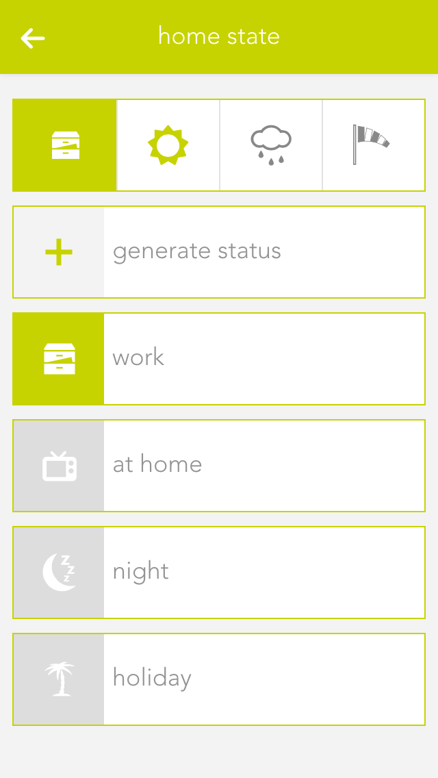
The “house status” displays the current status of your house and lets you change it.
The “house status” is located under “all apps” – “house status”.
If you want to activate a status via the visualization, you can do this either in the left-hand area of the corresponding object panel or via the operator panel using the button “execute”.
The status that is currently active is displayed both in the object panel and in the house status panel. If you drag the house status to your favourites, then the current active status is displayed there too.
The house status panel not only displays the current status of your house, but also if dawn/dusk, rain or wind are active. You can configure where this information comes from in the “global settings”.
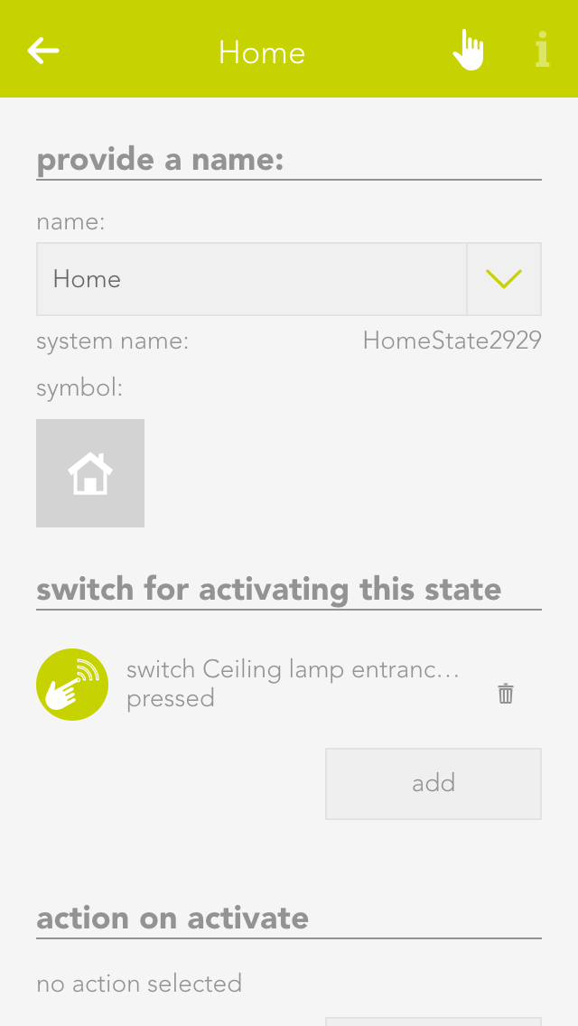
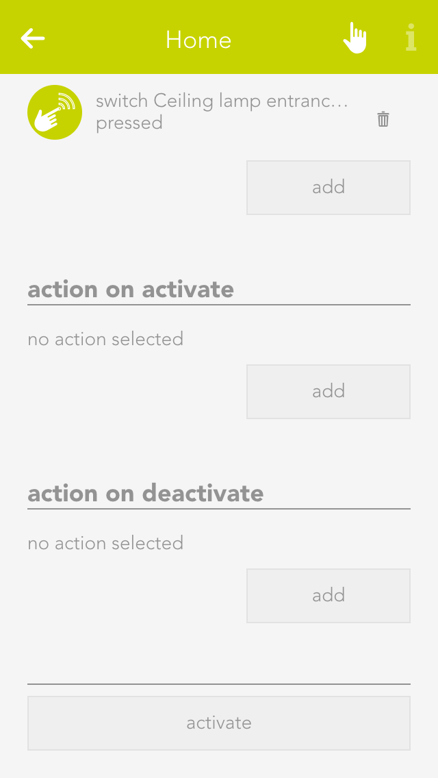
You can easily add a new status for your evonHOME. To add a new house status, click on the element “create status”. The operator panel opens and lets you first allocate a name to your house status. Once named, you can then continue with the configuration (described below).
Each status can be given a name and an icon that is displayed in your evonHOME.
For each of your created house stati, you can define which button activates it and should happen if the status changes.
Button to activate this status
Select the button here that allows you to activate the corresponding status
Action when activated
Select here the action that is to be invoked when the corresponding house status is activated.
Action when de-activated
Select here the action that is to be invoked when the corresponding house status is de-activated
Um die Türsprechanlage im evonHOME einbinden zu können, muss sich diese im selben Netzwerk wie Dein evonHOME System befinden.
Sobald Deine Türsprechanlage montiert und an Dein Netzwerk angeschlossen wurde, kannst Du diese in dein evonHOME System einbinden.
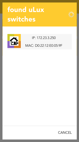
Lege dazu eine neue Sprechanlage über den entsprechenden Button an. Im nun erscheinenden Popup wird automatisch nach der Türsprechanlage gesucht. Sobald sie gelistet wird kannst Du sie auswählen und hinzufügen.
Sollte Deine Türsprechanlage nicht automatisch gefunden werden, kannst du diese auch über den Button "Manuell" selbst anlegen. In diesem Fall musst Du die IP Adresse der Anlage kennen und sie in den Einstellungen eintragen.
Eine neue Sprechanlage ist nun angelegt and kann konfiguriert werden.
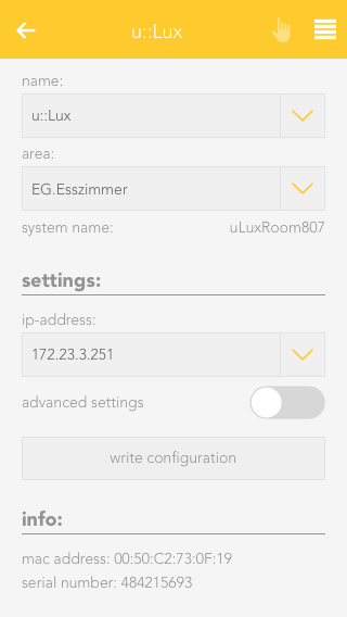
Wurde Deine Sprechanlage automatisch im Netzwerk gefunden und hinzugefügt musst Du die IP Adresse in den Einstellungen nicht mehr angeben.
Deine Sprechanlage wird sofort nach dem Anlegen vom System konfiguriert und startet von selbst neu. Es kann 1-2 Minuten dauern, bis der Vorgang abgeschlossen wurde und die Sprechanlage wieder verbunden ist.
Wurde die Sprechanlage manuell von Dir angelegt, musst Du in die Einstellungen gehen und die IP Adresse eintragen. Nutzername und Passwort sind bereits ausgefüllt, können aber jederzeit geändert werden, falls Du diese in der Türsprechanlage angepasst hast.
Wenn die Sprechanlage manuell hinzugefügt wurde, wird sie nach dem Eintragen nicht automatisch konfiguriert und startet daher nicht von selbst neu. Dadurch kannst Du auch bereits konfigurierte Sprechanlagen in das System einfügen, ohne das die Einstellungen erneut übertragen werden müssen.
Wenn Du eine neue Sprechanlage manuell hinzufügst, musst Du daher nach dem Eintragen der IP Adresse in den Abschnitt "Erweiterte Parameter" navigieren und den Punkt "Sprechanlage Konfiguration zurücksetzen". Nach dem anschliessenden Neustart der Türsprechanlage ist diese betriebsbereit.
Es ist wichtig, dass die Konfiguration der Sprechanlage durchgeführt wird, da erweiterte Funktionen wie die Erkennung der Klingel- und Licht-Tasten sonst nicht funktionieren.
If you want to be able to use the built in microphone and speaker of your intercom to talk to visitors, we recommended to download and use the following apps:
iOS - https://itunes.apple.com/at/app/mobotix/id527836206?mt=8
Android - https://play.google.com/store/apps/details?id=org.abionix.axviewer&hl=de
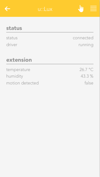
Wurde die Verbindung mit der Sprechanlage erfolgreich hergestellt siehst Du im OperatorPanel das aktuelle Videobild.
Über das Pfeilsymbol auf dem Bild kannst Du dir auch eine vergrößerte Version der Übertragung ansehen.
Falls die Sprechanlage manuell hinzugefügt wurde und Du noch die IP Adresse eintragen musst, erscheinen hier statt der Videoübertragung die betreffenden Eingabefelder.
Da die Türsprechanlage auch über eine Klingeltaste verfügt, kannst Du sie mit einer Tür verknüpfen. Navigiere dazu in die Tür App und wähle eine passende Tür aus. In den Einstellungen kannst Du nun die Sprechanlage hinzufügen. Wird die Klingeltaste betätigt, erhältst Du eine Benachrichtigung mit dem aktuellen Videobild. Außerdem wird eine Aufnahme des Kamerabilds gespeichert. Wenn Du einen Türöffner besitzt, kannst Du diesen in dem im evonHome System erscheinenden Popup bedienen.
Du kannst die Klingel und Lichttaste der Sprechanlage auch als Auslöser für das Erstellen von Szenen in der betreffenden App verwenden.
Das ObjectPanel der Sprechanlage kann auch über das Menü, das erscheint, wenn Du mit Deinem Finger bzw. der Maustaste länger auf dem Element bleibst/gedrückt hältst, vergrößert werden. Dadurch wird hier ebenfalls das Kamerabild eingeblendet.
Du kannst die Sprechanlage auch auf deinen Startbildschirm legen um so das Kamerabild immer sichtbar zu haben.
Sollte es zu Problemen bei der Erkennung der Klingel- oder Lichttaste der Sprechanlage kommen, kannst Du folgende Punkte überprüfen.
Damit das Betätigen der Sprechanlage Tasten in evonHOME erkannt wird, muss diese zuerst in evonHOME eingebunden werden. Die notwendige Konfiguration geschieht automatisch im Hintergrund, sobald Du die vom System gefundene Sprechanlage hinzufügst. Sollt es sich um eine Sprechanlage handeln, die mit einem Tastenfeld verwendet wird, musst Du im SettingsPanel unter "Erweiterte Parameter" den Punkt "Sprechanlage mit Tastenfeld Konfiguration zurücksetzen" wählen. Das kannst Du entweder bei einer bestehenden Sprechanlage durchführen oder wenn Du sie manuell hinzufügst.
Weitere Einstellungen sind für die Erkennung der beiden Tasten der Sprechanlage nicht notwendig. Sollte die IP Adresse der evonHOME Engine später geändert werden, muss die Sprechanlage über das SettingsPanel wieder zurückgesetzt werden.
Überprüfung Konfiguration
Im Settingspanel der Kamera kann unter "Erweiterte Parameter" sowohl die Klingel- als auch Lichttaste geprüft werden. Ist die Konfiguration der Mobotix Sprechanlage korrekt, werden zugehörige Events ausgelöst bzw. die Anzeigen auf dem ObjectPanel aktiviert.
Sollte dies fehlschlagen, können folgende Einstellungen im Webinterface der Sprechanlage überprüft werden:
1 - Navigation in das Admin Menü zu "Profile für Netzwerkmeldungen".
2 - Hier müssen sich Einträge für "Doorbell" sowie "LightSwitch" befinden. Jeder Eintrag enthält eine Zieladresse die mit der IP Adresse der evonHOME Engine übereinstimmen muss, sowie den vorgegeben Port "4500". Im Bereich "Datenprotokoll" befindet sich außerdem ein Eintrag für den "CGI"-Pfad, der den Systemnamen der Sprechanlage in evonHOME enthält. Dieser kann im SettingsPanel kontrolliert werden und muss mit dem hier eingetragenen Systemnamen übereinstimmen.
3 - Navigation in das Setup Menü zu "Ereignisübersicht"
4 - Im Bereich "Signalereignisse" muss es je einen Eintrag für die Klingel- sowie Lichttaste geben. Hier ist darauf zu achten, das diese nicht auf "Inaktiv" gesetzt sind.
5 - Navigation in das Setup Menü zu "Aktionsgruppen-Übersicht".
6 - Hier muss es ebenfalls Einträge für die Klingel- sowie Lichttaste geben. Unter "Bearbeiten" finden sich im Bereich "Ereignisauswahl" alle möglichen Signale, die als Auslöser dienen. Hier muss "CameraBellButton" für die Klingel- bzw. "CameraLightButton" für die Lichttaste ausgewählt sein (Passend zu den Signalen aus Punkt 4). Unter "Aktionen" muss die zugehörige Netzwerkmeldung aus Punkt 2 erscheinen.
The Internet weather app lets you call up data for a specified region and use it for your evonHOME.
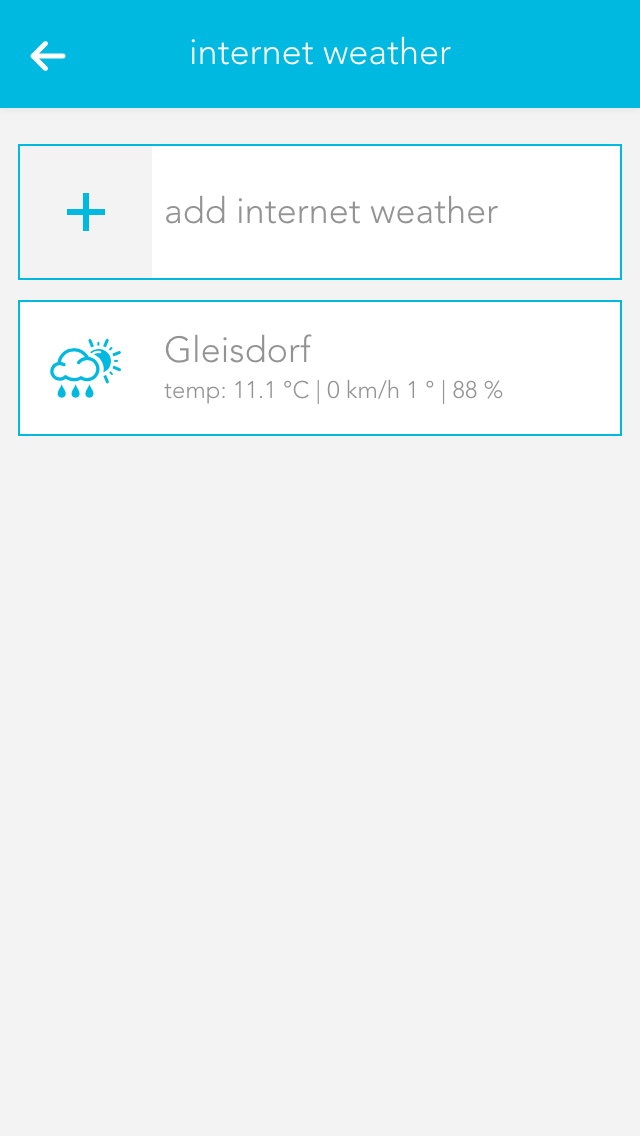
The app “Internet weather” is located under “all apps” – “Internet weather”.
Click on the element “add weather station” to add a new weather station. This opens the operator panel where you need to define a name for your weather station. Enter the API key and your location in the item “weather underground API key”. This is provided by WeatherUnderground (http://www.wunderground.com) once you have registered there. Once you have done this successfully, you will receive weather data for the specified location.
If you want the use this weather station for your evonHOME, then drag this weather station to the first position for wind, rain, outside temperature and daylight in the app “global priorities”. (For example, if you only want to use the outside temperature of this station, then only drag the weather station to the first position for the outside temperature).
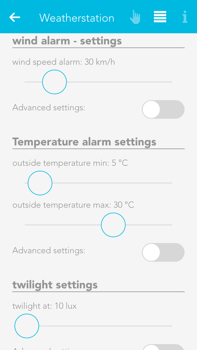
Wind alarm settings
This is where you define the wind speed that you wish to trigger an alarm. If you also wish to define hysteresis and a delay, then activate the option “extended settings” and select hysteresis and delay. If the wind speed exceeds the value defined for wind alarm, then the alarm is triggered. Now the wind speed must fall below the defined hysteresis value (below the wind speed alarm value) for the alarm to be reset. The delay defines how the wind speed must be above the defined limit for the alarm to be triggered.
Offset
If you are not satisfied with the time for sunset and sunrise, you can change then by activating the option “change sunrise and sunset times” and changing the times accordingly.
The logic app enables you to execute complex operations for which there is no app. For example, this could be controlling the ventilation of the WC, controlling a light transformer etc. If you wish to use logic, then you should already have a basic understanding. If you are new to the area of logic, exercise caution when using this feature.
The logic app is located under “all apps” – “logic”.
To create a logic sequence, you first need a logic program. This is comparable to a network in PLC programming. A program contains logic elements that you can use for your controller. For example, if you have a controller for the WC ventilation and one for a light transformer, then you can create an individual program for every controller.
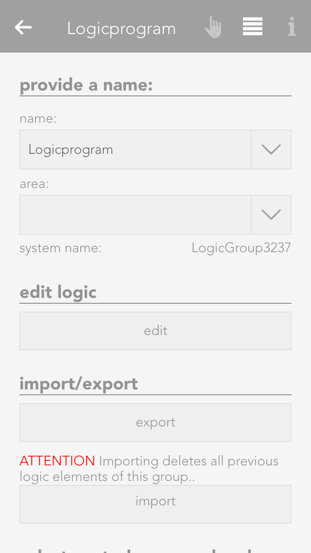
To create a logic program, open “logic” and select “add program”. This opens the operator panel for the logic program. You must first allocate a name to your program and optionally a room for it.
The operator panel for the logic program contains an item “parameter” where all parameters available to rapidly configure the program are listed (parameters are described in the chapter data elements). The values of these parameters are not lost if a controller fails.
The item “status” displays a diagram that shows you the time required to execute this program.
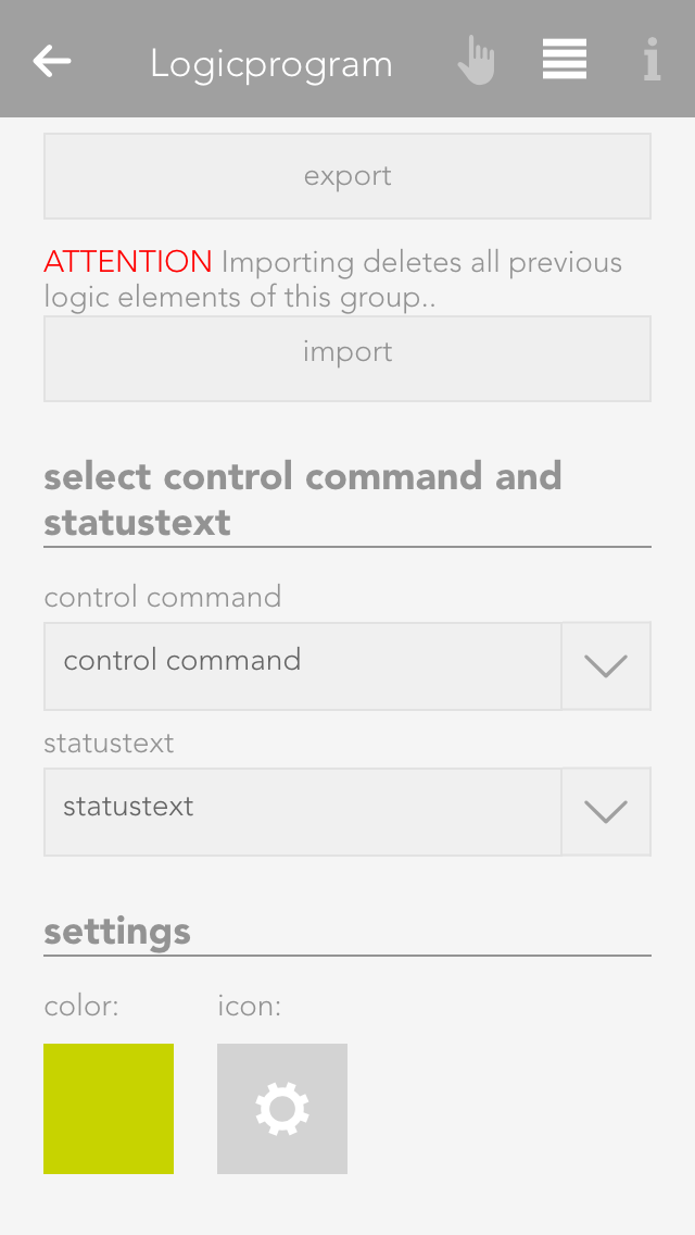
Every logic program can contain a control command and a status text. You can select a data element of type bool for the control command and a data element of type string (text). To do this, go to the parameter panel and select “choose control command and status text”.
The control command is intended to activate and deactivate the logic program via the object panel. You can toggle the control command via the icon on the left-hand side of the object panel.
The status text is displayed in the object panel under the name of the program. An example would be “ventilation will be switched off in 2 mins”.
If you want to edit the logic in this program, click on the button “edit” in the parameter panel under the item “logic”.
Each logic program allows you to define in- and outputs, which are shown in the linkpanel of a program. Defined in- and outputs can then be linked to values of other evonHOME apps.
This makes it possible to create interfaces for your logic program which make it easy for you to integrate it without the need to modify or edit the underlying logic construct. It is also very useful if you want to reuse it for different purposes as you only have to adapt the linked values.
To define an in- or output for your logic program, select a data element and change the type to "Input" or "Output".
It will then be listed in the linkpanel of your logic program and can be connected to other apps/values.
If you wish to save the logic program, you can do this via the button “export” in the parameter panel under the item “import/export”.
To import a logic program, click on the button “import” (directly under the “export” button). Note that any existing logic is overwritten by the logic in the imported program. Furthermore, if logic elements were linked across programs prior to export, after importing, the links no longer exist.
You can allocate a colour and icon to your logic program. Do this in the parameter panel under the item “settings” by clicking on the current colour or icon.
Elements are all logic elements that you can add to a logic program (AND, OR, etc.)
To create a logic element, you must first be located in the logic program. If not, open the logic program and select the item “edit logic” in the parameter panel. Then add new logic elements to the program using “add function”. To do this, click on the corresponding element.
If a logic element has an error, or if it is simply not activated, then you can recognize this due to the colour of the element.
Green
The element is working fine.
Orange
The output of this element is being simulated.
Grey
The element does not have a fault, but it is deactivated.
Red
The element has a fault: either an input has no value, or the output it is linked to no longer exists.
The operator panels for each logic element (except for data elements) are all constructed using the same principle. The first item is the setting (if available), then the inputs, then the output.
This shows you the selection of an input.
The button “select” lets you select the output of a different logic element that you wish to connect to this input.
The checkbox under “invert” lets you invert the input (if it is of type bool).
The checkbox under “fixed value” lets you allocate a fixed value to the input. This means that if you activate this checkbox, the type bool displays a checkbox in the centre with the text “value”. The state of the input can be controlled using this value. If you activate this checkbox for an input of data type number or string, then an input field appears where you can enter the desired value.
Data elements are intermediate stores for values. This means that data elements can be described by other logic elements by selecting this data element at the output (however only if both are of the same type). Data elements can also be linked with inputs of other logic elements. Every data element has the option “parameter” in the operator panel. If you have activated this option, then you can see this data element in the operator panel of the corresponding logic group and you can change it from there. This has the advantage that you do not always have to have the logic program open to change a value. Parameters also means that the value of a data element remains even if the controller were to fail.
You can change the value of any data element via the object panel. You can do this on the left-hand side of the object panel for types bool and number, and on the right-hand side via the input field for type string.
The element “AND” is a classical AND operator. This means the output is set to true as soon as ALL inputs are true. This element can have between 2 and 6 inputs. The number of inputs can be changed via the operator panel using the buttons “add pin” and “remove pin”.
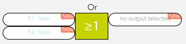
The element “OR” is a classical OR operator. This means the output is true as soon as at least one input is true. This element can have between 2 and 6 inputs. The number of inputs can be changed in the operator panel using the buttons “add pin” and “remove pin”.
The compare function works by comparing the values present at the two inputs and switches the output accordingly.
You can change the following settings in the operator panel:
Type
Select the type of comparison
Hysteresis
If you require hysteresis, you can define it here.
Sample time
This is the time for which the comparison must be fulfilled for the output to be switched to true.
The time relay lets you delay an output switching on or off, or leave it switched on for a certain time.
The time relay has two types that you can configure under “select used times”.
Delay switching on/off
If the input is true, the output is only set to true after the selected ON time delay. If the input jumps from true to false, the output is set to false after the selected OFF time delay.
Switch on delay and duration
This enables the option “input as flank”. If you have not activated this option, then the input must be true for at least the switch on delay time in order for the output to be set true for the defined duration and after this duration (independently of the input) reset to false. If you have activated this option then a flank is sufficient on the input and the output is set to true for the defined duration and then reset to false.
Time measurement is represented by a stopwatch. Time measurement can be started, stopped and reset via inputs “activated” and “reset”.
If the input “activated” moves from false to true, the stopwatch starts. If the input “activated” moves from true to false, the stopwatch stops, if “auto reset” was NOT activated.
If “auto reset” is activated, then the stopwatch is reset when the input “activated” moves from true to false.
The input “reset” resets the stopwatch. This only works if “auto reset” has not been activated.
Mit der Wertzuweisung kann ein beliebiger Wert dem Ausgang zugewiesen werden.
The value on the input E1 is written unchanged to the output if “activated” is true.
The counter can increase, decrease or reset a numerical value to 0.
The input “up” increments the counter by one when the input changes from false to true, the input “down” decrements the counter by one and “reset” resets the counter to 0.
Flank recognition allows rising and falling edges to be evaluated. This means that if the selected flank appears on the input, then the output is set to true for one cycle and then reset to false.
The type of flank can be selected in the operator panel under the item “settings”.
The function generator enables periodic square wave signals to be generated.
As soon as the input “activated” is true, the function generator is started and generates a periodic square wave signal on the output.
“TOn” can be used to adjust how long the square wave signal is true and “TOff” how long it is false.
A function element is used to carry out mathematical calculations. “A1” must contain the desired calculation.
The variables E1 to E6 can be used for the calculation, e.g. A1 = 2*E1 + E2.
As soon as the input “activated” is active, the calculation will be carried out. The buttons “add pin” and “remove pin” can be used to add up to 6 inputs. The following shows link shows you which operations are possible:
Documentation- Functions(https://developer.mozilla.org/de/docs/Web/JavaScript/Reference/Global_Objects/Math)
For as long as the input is true, the output of the reset element will be set to false.
For as long as the input is true, the output of the set element will be set to true.
The SR flip flop is used to set and reset an output. If the input “set” is true, then the output is true. If the input “reset” is true, the output is false. If both inputs are true, then the output is false. If both inputs are false, the output is stored, meaning it remains in this state until the input is true again.
The text block is used to create any text string you want.
1 to 6 inputs (E1 – E6) can be created using the buttons “add pin” and “remove pin” and the text from these inputs are then strung together.
For example, if the text for E1 is “It is now ” and the text for E2 is the current time (use the button “select” and under “system” then “time”), then the following text string will be created “It is now 17:00”.
This is a clocked PI controller where you supply demand value, actual value and clock.
The settings for the PI controller are located in the parameter panel.
Task
If the light in the WC is switched on, then the ventilation should be switched on 15 seconds later (the ventilator must be connected to a digital output) and run for one minute after the light has been switched off. If the light is switched off before the ventilator is switched on, the ventilator should not be activated.
Solution
First open the app “logic” and create a logic program via “add program”.
Give the logic program the name WC-ventilation and select the room WC.
Open the logic program via the button “edit”. Use the “add function” to add the function time relay. This relay is red, meaning that it isn’t yet working, because there are no inputs.
Now open the time relay. Since the output should be switched on after 15 seconds, you will need a delay of 15 seconds. Change the switch on delay to a fixed value and enter the value 15. Do the same for the switch off delay, except instead of 15, use the value 60, since the ventilation is only meant to run for 1 minute (= 60 seconds) after the light has been switched off.
Now you need to link inputs and outputs. Select input E1 using the button “select” and navigate to the lights, select the WC light and select “light on”. In the object panel of the time delay, you can now see the current value of the light and how it changes when the light is switched on and off. Now all you need to do is connect the output of the time relay with the digital output. To do this, click on “select” under “output” and navigate to the digital outputs. Once there, select the desired output and click on “set value”.
Now you can test your WC ventilation and see if everything is working fine.
Task
There are 4 lights and 1 light transformer available. The light transformer is connected to a digital input. As soon as at least one light is switched on, the light transformer must be switched on. If no lights are switched on, the light transformer must also be switched off.
Solution
The first thing to do is open the app “logic” and create a logic program via “add program”.
Give this logic program a name “light-trans”.
Next, open the logic program using the button “edit”. Use the button “add function” to add an OR. This OR is red meaning that it is not currently functioning, because it has no inputs.
Now open the OR and add two inputs using the button “add pin”. These four inputs must now be linked with the four lights via the button “select” by selecting “light switched on” for each light. The OR is now green, because all inputs are linked. Finally, you need to connect the digital output of the transformer with the OR. Do this by clicking on “select” under “output”, open the digital output there and select “set value” for the desired digital output.
The logic should now work as desired.
Task
You measure humidity in a room and want to switch on the ventilation as soon as the humidity has reached a certain value.
Solution
To do this, the humidity sensor must be connected to an analog input of an analog module and configured accordingly (to do this, see chapter “Analog Input”). The ventilation must be connected to the output of a digital module.
Next, create a logic program in the app “logic” using “add program”. Give the program a meaningful name (e.g. fan control) and if wish, allocate a room. Then open the parameter panel and select “edit” under “edit logic”. Insert a compare function via “add function”.
Now open the operator panel of the compare function. Under the item “settings”, first select for “type” the value “greater than” (since the fan is to be switched on when the humidity is GREATER than a certain value). You can configure the hysteresis for the compare function as you feel is necessary. In this example, select 5 for the hysteresis. The sample time can be left at 0. Now the compare function is correctly configured.
The inputs and output now need to be connected. Select the analog input you connected the humidity sensor to under “inputs” for “E1”. For “E2” enter the value above which the fan is to be switched on. In this example select 80. Now select the digital output you connected the fan to using the button “select” under “output”.
The ventilation control is now complete. If you want, you can change the hysteresis and the sample time as you require.
The “mixer circuit control” app is an external temperature heating control loop. The “mixer circuit control” is used to configure and control 3-way heating mixer valves.
These functions are located under “all apps” – “mixer circuit control”.
Click on the element “add mixer control” to create a new mixer circuit controller. The next step is to give your mixer circuit control a name, and then you can continue with the configuration.
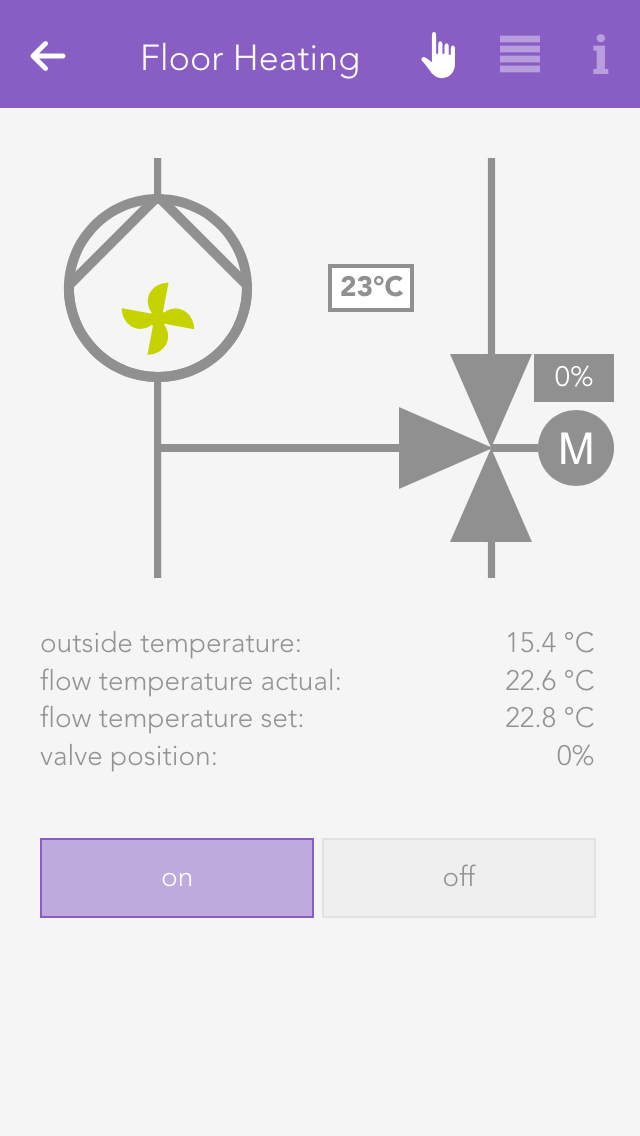
The operator panel displays a schematic of the control. This diagram shows you whether the pump is on (screw in the pump is green and rotates) or off. Displayed adjacently is the current temperature of the feed line and to the right the current position of the mixer valve and whether it is open or closed.
All relevant values pertaining to your mixer circuit control are displayed below this.
If your mixer valve is unreferenced, i.e. the current position of the valve is unknown, then the button “execute reference” is displayed. Clicking on it closes the valve completely; hence the current position is known. The mixer circuit control must be fully configured before a reference can be executed.
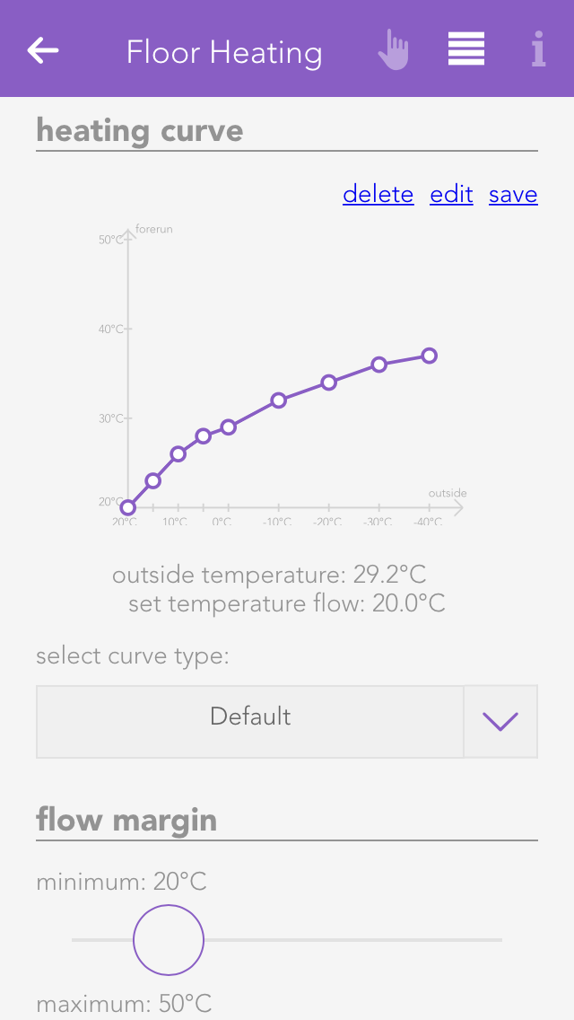
The heating curve allows you to adjust the desired temperature of the feed line as a function of the outside temperature.
There are pre-defined curves you can select from using “select curve type”. If there is no pre-defined curve that entirely suits your needs, then you can edit the pre-defined curves by clicking on “edit”. The selection then jumps to “user-defined”. If you wish to save your curve, click on “save”. Saved curves can be deleted using “delete”. When selecting points, you are limited on the one hand by the minimum and maximum feed line temperature, and on the other by the previous and subsequent point. For example, the point at 10 °C outside temperature cannot have a lower feed line temperature than the point at 15°C and a higher temperature than the point at 5°C.
If the outside temperature reaches a value outside of the curve, then the curve is continued horizontally. This means if the curve were to end on the left-hand side at an outside temperature of +20°C with a corresponding feed line temperature of +22°C, then the feed line temperature for outside temperatures higher than +20°C will remain +22°C.
To be able to process outside temperatures higher than +20°C, the cooling operation must be activated under “all apps” – “settings” – “room climate”. Warning! Cooling operation may only be activated if the heating is really able to cool, since in cooling mode, the mixer outputs are switched exactly the opposite way.
You can define your minimum and maximum feed line temperatures here.
Über diese Einstellung kannst Du die maximale Temperatur, die im Rücklauf vorhanden sein darf, regulieren. Wird die eingestellte Temperatur überschritten, wird das Ventil geschlossen bis die Temperatur wieder unter dem vorgegebenen Wert liegt.
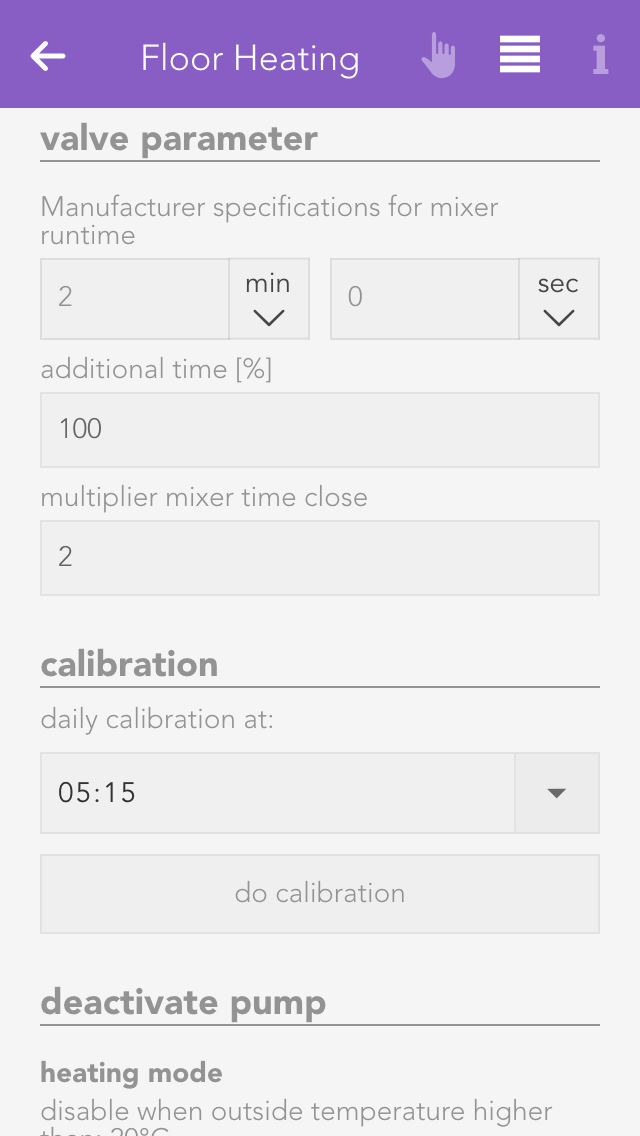
Enter the runtime for the mixer valve in seconds according to the manufacturer in “manufacturer mixer valve runtime [s]”. If the value you entered was correct, then you must now click on the button “execute reference run”. Please note that you must have previously correctly set the inputs and outputs.
The field “overrun time” lets you how much longer in percent the mixer output remains switched on when completely open or closed. This guarantees that the mixer is subsequently really completely open or closed.
Since a mixer valve normally requires longer to close than to open, you can use the “multiplier mixer closed” to define how much longer the valve needs to close than open.
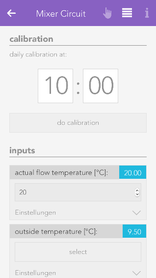
Since there is always a certain error when opening and closing the valve, a calibration run must be run daily. All you have to do is set the desired time for this to occur and the rest is done automatically.
Feed line actual temperature
Select the input here that measures the actual temperature of the feed line.
Outside temperature
Select here the input used to measure the outside temperature. The standard setting is located in “system” – “house status” – “outside temperature”.
Release
Select the main switch for the mixer control. This input is used to activate or deactivate the entire control.
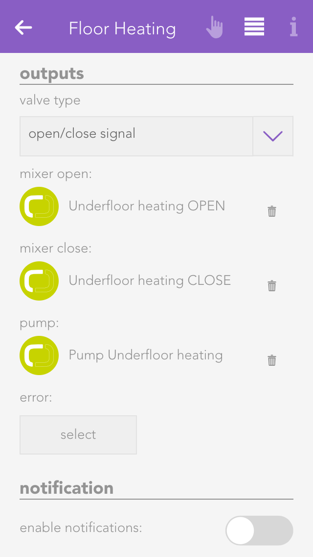
Valve Type
The used valve type is chosen here. The options are analog with "0-10V signal" and digital "open/close signal".
Valve
(With valve type "0-10V signal")
Select the analog output, which will be used for the valve control.
Mixer open
(With valve type "Auf/Zu signal")
Select here the output used to open the mixer valve.
Mixer closed
(With valve type "Auf/Zu signal")
Select here the output used to close the mixer valve.
Pump
Select the output used to connect the mixer pump.
Fault
Select an output to be switched if there is a fault.
In diesem Abschnitt kannst Du die automatische Abschaltung der Pumpe einstellen, wenn von Dir festgelegte Temperaturen über- oder unterschritten werden.
Hier kann der Absenkbetrieb konfiguriert werden. Bei aktiviertem Absenkbetrieb wird die Heiz- oder Kühltemperatur/leistung um den verknüpften Wert verringert.
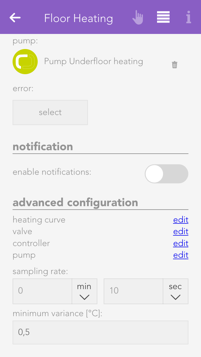
The extended configuration allows you to configure all the components of your mixer control extra. Simply click on “edit”. Exercise caution, particularly when adjusting the controller parameters.
Below this, you can adjust the sample time and minimum error.
Sample time
This is the time period when a new position of the valve is calculated (standard 10s).
Minimum error
The position of the valve is only adjusted if there is a difference between desired and actual temperature of the feed line. If the difference (error) is larger than this value, then the position of the valve is changed.
Activate notification
If you wish to receive a notification of a fault condition, then activate this option.
Bevor die Kommunikation zwischen evonHOME und Deinem Modbus Gerät hergestellt werden kann, muss dieses zuerst in dein Netzwerk integriert werden. Lies dazu am besten die Anleitung des betreffenden Geräts, welche auch Informationen über die möglichen schreib-/lesbaren Werte enthalten sollte sowie über betreffende Modbus Register.
Hast Du dein Modbus Gerät erfolgreich in Betrieb genommen, kannst Du damit beginnen, es in Dein evonHOME System zu integrieren.
Wähle hierzu "Neues Gerät hinzufügen".
Dadurch wird ein neues Modbus Gerät im System angelegt und kann konfiguriert werden.
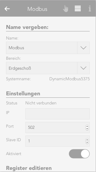
In den Einstellungen des neu erstellten Modbus Gerätes solltest Du als erstes einen Namen und einen Raum vergeben.
Anschließend musst Du die Netzwerk Adresse (IP, Port) sowie SlaveID des Modbus Geräts eingeben.
Wurde die Verbindung erfolgreich hergestellt, ändert sich der angezeigte Status von "Nicht Verbunden" auf "Verbunden".
Als Nächstes benötigst Du die gerätespezifischen Informationen über les-/schreibbare Register, auf die Du mit der evonHOME Modbus Schnittstelle zugreifen kannst.
Diese musst du den Unterlagen deines Modbus Gerätes entnehmen.
Hast Du alle benötigten Informationen gesammelt, ist es an der Zeit, die passenden Register anzulegen. Navigiere zu dem Bereich "Register editieren" und wähle "Editieren".
Du befindest dich nun in der Registeransicht, in der Du neue Register hinzufügen oder anpassen kannst.
Es stehen Dir hier 4 verschiedene Registerarten zu Verfügung:
Coil Status (1 Bit, Lesen-Schreiben: FC=01)
Einzelner Ein-/Ausgang.
Holding Register (16-Bit, Lesen-Schreiben: FC=03)
Analoger Ein-/Ausgang.
Input Register (16-Bit, Nur Lesen: FC=04)
Analoger Eingang.
Input Status (1 Bit, Nur Lesen: FC=02)
Einzelner Eingang.
Welche Register für Dein Modbus Gerät verwendbar sind, sowie deren Konfigurationsdaten (Adresse, Datentyp, Lese-/Schreibzugriff) musst Du den Informationen entnehmen, die Deinem Gerät beiliegen.
In den Einstellungen jedes angelegten Registers müssen diese anschließend eingetragen werden.
Neben den spezifischen Konfigurationsmöglichkeiten für jedes Register, kann auch festgelegt werden, ob der Zugriff "Lesend" oder "Schreibend" erfolgt. Bei Schreibzugriff erscheinen in der Bedienoberfläche des Registers sowie des angelegten Modbus Gerätes in evonHOME zusätzliche Bedienelemente über die die geschriebenen Werte verändert werden können.
In den Einstellungen des im evonHOME System angelegten Modbus Gerätes kannst du die Konfiguration deiner Register exportieren und damit sichern, um sie später wieder importieren zu können (auch in ein anderes evonHOME System).
Zusätzlich lässt sich einer der Register als Anzeigewert auswählen, welcher im ObjectPanel deines Modbus Gerätes sichtbar ist und Farbe sowie Icon ändern.
Die Statuswerte und Bedienelemente aller angelegten Register erscheinen im OperatorPanel des Modbus Gerätes. Nach der Konfiguration kann das Gerät hier gesteuert und ausgelesene Werte kontrolliert werden.
Neben der Bedienung über diese Ansicht, kann auch innerhalb der evonHOME Logik App auf alle Register zugegriffen werden.
Dadurch lassen sich komplexe Abläufe umsetzen.
Wenn Du ein angeschlossenes Audiomodul besitzt, kannst Du es mit Hilfe der App "Musik" steuern. Jedes Audiomodul, bietet 4 einzelne Ausgänge an denen Du Lautsprecher anschließen kannst, welche dann über die "Musik" App konfiguriert werden können. Außerdem ermöglicht dir dieses Modul die Wiedergabe von Musik aus bis zu 4 verschiedenen Quellen.
Du findest die Anwendung unter 'Alle Apps' - 'Musik'.
Sobald ein neues Audiomodul an Dein evonHOME System angeschlossen wurde, kannst Du bereits mit der Konfiguration deiner Lautsprecher und Quellen beginnen. Befolge dazu folgende Schritte:
Bevor Du die einzelnen Quellen und Lautsprecher an Deine Wünsche anpassen kannst, solltest Du zuerst ein paar grundlegende Einstellungen für dein Audiomodul vornehmen.
Navigiere dazu nach 'Alle Apps' - 'Hardware', wo Dein neues Audiomodul gelistet wird.
Öffne nun die zugehörigen Einstellungen durch einen Klick auf den Namen des Moduls.
Hier solltest Du zu allererst festlegen, wie Du Deine Lautsprecher verwenden willst. Du hast die Auswahl zwischen Mono oder Stereogruppen, kannst aber auch alle 4 Lautsprecherausgänge als gemeinsame Gruppe zusammenfassen.
Je nachdem, welche Auswahl Du hier triffst, erscheinen betreffende Lautsprecher in der Musik-App.
Einige Lautsprecher sollten nur mit einer gewissen maximalen Lautstärke betrieben werden um diese nicht zu beschädigen. Daher hast Du hier die Möglichkeit sowohl die maximale als auch die minimale Lautstärke für alle angeschlossenen Lautsprecher einzustellen.
Darüber hinaus werden hier auch Diagnoseinformationen angezeigt und das Audiomodul kann neu initialisiert werden.
Hast Du alle Einstellungen durchgeführt kannst Du bereits zu 'Alle Apps' - 'Musik' navigieren, wo Du nun alle verfügbaren Quellen sowie Lautsprecher wiederfindest.
Jedes Audiomodul verfügt über vier verschiedene Quellen, welche Deinen Lautsprechern zugewiesen werden können. Während "FM-Radio" und "Aux" fest vorgegeben sind, kannst Du für die übrigen zwei zwischen mehreren Optionen wählen.
Zur Auswahl stehen:
Du solltest hier eine Auswahl treffen, damit Du diese Quellen verwenden kannst.
Je nach gewählter Option stehen dir verschiedene Möglichkeiten zur Bedienung zur Verfügung. So kannst du bei "Internet Radio", "Medienserver" sowie bei den "Lokale Dateien" durch die Liste an verfügbaren Medien/Sendern navigieren und Favoriten setzen. Im Falle von Airplay lässt sich der Name ändern, der bei einer Suche auf deinem Endgerät angezeigt wird.
In den Einstellungen jeder Quelle hast Du außerdem die Möglichkeit einen oder mehrere Lautsprecher für die Ausgabe zuzuweisen sowie die aktuelle Ausgabe zu überprüfen und mittels entsprechender Buttons zu steuern.
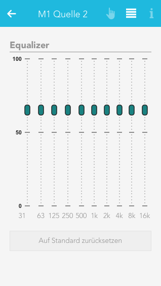
Zur zusätzlichen Anpassung der Audiowiedergabe, steht dir im Parameterpanel der anpassbaren Quellen noch ein Equalizer zur Verfügung
Je nachdem, welche Einstellungen (Stereo und Mono Gruppen) Du bei der Konfiguration deines Audiomoduls vorgenommen hast , werden Dir zwischen 1 und 4 Lautsprecher angezeigt.
Im OjectPanel deines Lautsprechers werden die Informationen über die aktuelle Medienwiedergabe angezeigt. Darüber hinaus kannst du hier auch die Lautstärke verändern, wenn du die passende Panelgröße eingestellt hast.
Du kannst jedem Lautsprecher eine von den verfügbaren 4 Quellen zuweisen. Wurde eine Quelle ausgewählt, siehst du im unterem Bereich der Anzeige was gerade gespielt wird und kannst die Lautstärke anpassen.
Bei der Verwendung von Airplay als Quelle kann die Lautstärke der Wiedergabe zusätzlich über das verbundene Gerät gesteuert werden.
Es empfiehlt sich daher die Lautstärke des Lautsprechers etwas höher zu stellen oder anzupassen.
In den Einstellungen des Lautsprechers kannst Du wie gewohnt den Namen und den zugewiesenen Raum anpassen. Außerdem siehst du Informationen über den einzelnen Lautsprecher.
Darüber hinaus kannst Du Deinem Lautsprecher einen Taster zuweisen, über den die Wiedergabe gesteuert werden kann.
Die Geschwindigkeit, mit der die Lautstärke bei einem langen Tastendruck verändert wird, kann mit einem Schieberegler angepasst werden.
Möchtest Du, dass die Wiedergabe nach einer festgelegten Zeitspanne automatisch stoppt, kannst Du den "Sleep Timer" aktivieren und nach Deinen Wünschen anpassen.
The Netatmo App allows you to integrate your Netatmo Weatherstation and its Rain Gauge extension.
The Netatmo app is located under “all apps” – “Netatmo”.
Once inside the Netatmo app, you can add your weather station with "add Netatmo". There, you will have to enter your Netatmo credentials to link your account with evonHOME.
Confirm to proceed.
If your login was successful, the system will fetch all your Netatmo Weather Stations from your account and add them to your evonHOME.
The ParameterPanel of each Netatmo Device allows you to adjust its name and area as well as its displayed value, which will be shown in the ObjectPanel of the Device. For example, the Netatmo Base Station lets you select one of the following values:
Besides choosing a display value, you will also find a list of basic location information for the current Netatmo device, which are fetched from your Netatmo account.
The OperatorPanel of your Netatmo Device will list its aggregated data like noice, temperature, pressure and more.
It will also display the last time those values were loaded from the device.
At the bottom of the panel, you will find a diagram displaying all records for a selected value over a chosen time. You can change the value or timeframe via the provided dropdowns.
The Philips Hue App makes it possible to integrate Philips Hue lights into your evonHOME.
“Philips Hue” is located under “all apps” – “settings” - "Philips Hue".
Before you can use your Philip Hue lights inside evonHOME you will have to connect the Philips Hue Bridge to it. Make sure that the Bridge is on the same network as your evonHOME system and follow these steps.
Navigate to "All Apps" - "Settings" - "Philips Hue".
All Philips Hue Bridges which are connected to evonHome will be listed here. To add a new bridge to your system, use the "add new bridge" panel.
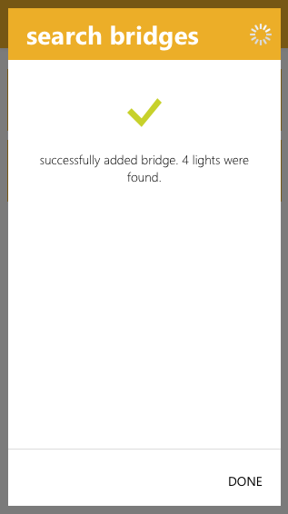
evonHOME will now start to search for all available Philips Hue Bridges inside your local network and lists them inside a popup.
Select the Philips Hue Bridge you want to add to evonHOME. You will be asked to press the link button on your Philips Hue Bridge to confirm the connection.
If the connection was established, you will be presented with a success message. You can close the popup now.
Your Philips Hue Bridge is now connected to your evonHOME system.
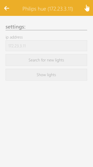
All Philips Hue lights, which are linked with the bridge, will also be added to your evonHOME system. In case you are changing your Philips Hue configuration in the future (adding or removing Philips Hue lights) you can use the "Search for new lights" button in the OperatorPanel.
Use the "Show lights" button to go to the list of all currently connected Philips Hue lights.
Notice that all connected Philips HUE lights will also be listed in the Lights App, which you can find under "All apps" - "Lights".
Besides adding the Philips Hue Bridge and its connected lights to evonHOME as described in section "Create" no further configuration is needed. In case you add or remove any Philips Hue lights in the future, you can navigate into the settings to the bridge and use the "Search for new lights" button in the OperatorPanel. This will search for new lights and add them to your evonHOME.
All connected Philips Hue Lights are added to the Lights App, which can be found under "All apps" - "Lights". They behave like RGBW lights and provide the same basic controls and functionality like changing color, adjusting brightness or creating scenes with the Scenes app.
The OperatorPanel of each Philips Hue light provides you with a color wheel for selecting the desired color and a slider for adjusting the brightness. You can also add the current color/brightness combination to your favorites and activate them on demand.
Starting with version 1.4, your evonHOME offers you a REST API Service at "http://[evonHOME_IP]/api". The following steps are required to use it.
To send requests to the REST API, you must authenticate yourself. A token is used for this purpose, which you will receive once you make a successful login attempt via the REST API.
"http://[evonHOME_IP]/login", with this header parameters:You will receive a token 'x-elocs-token' as a response, which will automatically be set as a cookie. This token will now be used as an authentification for all further requests.
Depending on from where you are sending your requests, the cookie will automatically be used. Otherwise, you will have to add the token to the header of every request 'Cookie:token=[Token]'.
The evonHOME REST API allows you check the status of the components in your system and to control them. The following requests are available to you:
GET: apps
"http://[evonHOME_IP]/api/apps"
Returns a list of all apps.
GET: apps/{fullName}
Returns detailed information about the requested app.
GET: instances
Returns a list of all instances.
GET: instances/{instanceId}
Returns detailed informations about the requested instance.
GET: instances/{instanceId}/{action}
Returns the current value of the requested property of a specific instance. For example, the current state of a light.
POST: instances/{instanceId}/{action}
Calls a method of the specific instance.
You can find a test interface at "http://[evonHOME_IP]/api", which allows you to try out all listed requests.
In the following example, we want to switch a light by using the REST API.
Before we can start, we have to make sure that the preparations for authentification are done (see topic "Preparation" and "Authentification"). With the received token, we are now able to send all requests and commands.
At first we send a GET request to `"http://[evonHOME_IP]/api/instances" and receive a list with all instances, which are currently active in the evonHOME system.
"statusCode": 200,
"statusText": "success",
"data": [
{
"ID": "SC1_M04.Light1",
"ClassName": "SmartCOM.Light.Light",
"Name": "Roomlight",
Group": "AreaOutdoor
},
...
]
}```

As we want to switch a light, we choose the 'Roomlight' and use its "ClassName": "SmartCOM.Light.Light" to send a GET request to `"http://[evonHOME_IP]/api/apps/SmartCOM.Light.Light"` and receive the available methods and properties.

```{
"statusCode": 200,
"statusText": "success",
"data": {
"methods": [
{
"parameter": [],
"name": "SwitchOn",
"type": 0,
"derived": false,
"tags": [
linkable
],
"returnType": "void",
"description": "switch light on",
"isStatic": false
},
...
],
"properties": [
{
"name": "IsOn",
"type": "boolean",
"remark": "light switched on",
"declaration": "2",
"derived": true,
"parameter": false,
"tags": [
linkable
],
"isStatic": false
},
...
],
"fullName": "SmartCOM.Light.Light",
"displayName": "Light",
"autoStart": false
}
}```

We are now sending a POST request to `"http://[evonHOME_IP]/api/instances/SC1_M04.Light1/SwitchOn"` with the following parameters in the header:
- instanceId: SC1_M04.Light1
- action: SwitchOn
- body: [ ]

This will call the specified method of the light and switch it on. We can also check the current status by sending a GET request to `"http://[evonHOME_IP]/api/instances/SC1_M04.Light1/IsOn"` and receive a response containing the current status, in this case 'true'.

```{
"statusCode": 200,
"statusText": "success",
"data": true
}```Die Sprachausgabe gibt Dir die Möglichkeit, von Dir eingegebene Texte über die an Dein evonHOME Soundmodul angeschlossenen Lautsprecher wiederzugeben.
Du findest die Anwendung unter 'Alle Apps' - 'Sprachausgabe'.
Bevor Du konfigurierte Texte über dein Soundmodul wiedergeben kannst, solltest Du zuerst bestimmen, welche Lautsprecher dafür verwendet werden sollen. Dies kannst Du in den Einstellungen der Sprachausgabe tun.
Hier hast Du außerdem die Möglichkeit einen Signalton zu aktivieren, der vor jeder Sprachausgabe abgespielt wird.
In der Bedienoberfläche der Sprachausgabe kannst Du den Text eingeben, der gesprochen werden soll. Außerdem ist es möglich, die Lautstärke der Ansage einzustellen.
Über den Button "Sprechen" wird die Wiedergabe auf den von Dir ausgewählten Lautsprechern gestartet. Darüber hinaus kannst du die Sprachausgabe auch in selbst erstellten Szenen verwenden, um Texte wiederzugeben.
The TCP Client app allows you to communicate with TCP-compatible devices (TCP clients). Among them are devices like beamers, TVs and many more. Additionally, you can use a gateway (TCP to serial port) to send commands to different devices with a serial port.
The TCP Client app is located under “all apps” – “TCP Client”.
To create a new TCP Client, navigate to the app and choose 'add TCP client'.
On every TCP Client, there is a symbol which shows you if there ist a working connection to the desired device. As you have to configure every new TCP Client first, the symbol will display a red X.
Before the TCP Client can communicate, you have to enter a valid IP address in the settings. To do so, open the Parameter panel of your newly created TCP Clients and enter the IP address and the port of the desired device.
If the IP address and port are correct and a successful connection could be established, you will see a green checkmark in the display of the TCP Client after some seconds.
The Operator Panel of the TCP Client displays the current status of the client, allows you to send preconfigured commands and shows you a list of recently received data.
State
The current status of the TCP Client will be shown here.In case there are any problems with the connection to the desired device or you haven't entered a correct IP address yet, a red X will be displayed.
Events
Every TCP Client allows you to create 3 events, which are triggered when the conditions meets. You can then link to those events in created scenes (inside the Scene app) and use them as triggers. Configured events will be displayed in this list.
Commands
All commands you have created are listed here. You can trigger or delete each one.
Last received data
This list will display recently received data. You can switch between a 'text' or 'hex' view.
The settings of the TCP Client allow you to configure new commands and events, which can be linked in scenes.
IP configuration
The IP address and port of the device for which you want your TCP Client to establish a connection to should be entered here. This settings should be the first configuration you make after creating a new TCP Client. The Operator Panel will then tell you if your connection is working.
Commands
If you want to create a new command, you can do this here by using the 'new command' button. Choose a name and the data which should be send. You can decide between simple text or hex values. Additionally, you can also decide whether you expect a specific answer and choose between text or hex values.
Test command
If you just want to test a command, you can do this here. The result will then be displayed beneath the 'test command' button.
Events
There are some devices, which may frequently send data, without the need for a explicit request (e.g. via a command). For such use cases, every TCP Client has 3 events. For each event, you can set what data you are expecting and their type (text or hex). If an expected event occurs this event will be triggered and can be linked to when creating a Scene.
The app allows you to configure the evonHOME uLux switch.
The uLux app is located under “all apps” – “uLux”.
Important: To integrate the uLux switch into evonHome, the required uLux design-template must be present on it. In delivery state, all evonHOME uLux switches already contain this template. Further configuration with the uLux software is not required.
To create a new uLux room, click on the add symbol, after which a search for uLux switches in your network is started. If the switch is not immediately found, you can just restart the search. Once the uLux is found, you just have to select it to add it to your system.
The uLux switch works like a room control. This makes it easy to add all elements from a room (lights, blinds, heating, scenes) to it.
Just add a name and room to your uLux switch and once you finish the configuration every element from this room will automatically be displayed on the switch.
If an uLux extension module is connected, your can find all measured values in the 'extension' section. Those values can also be linked in the Logic app.
After the uLux switch has been found, you only need to add a name, a room and an IP-address.
Settings
Here, you can change the network address of your uLux switch.
If you edit this settings, you will have to press the button 'write configuration' to transfer them to your uLux switch. The switch will then restart and boot up with your new configuration after some seconds.
Die Anbindung und Steuerung einer Lüftung an Dein evonHOME System erfolgt über digitale Eingänge und digitale oder analoge Ausgänge, je nachdem, was Deine Lüftung unterstützt.
Wurde die Lüftung an betreffende Ein- Ausgänge angeschlossen, muss sie in Deinem evonHOME System angelegt werden.
Wähle dazu "Lüftung hinzufügen".
Nun wird eine neue Lüftung erstellt und kann konfiguriert werden.
Nachdem Du eine neue Lüftung in evonHOME angelegt hast, solltest Du dieser zunächst einen Namen geben und sie einem Raum zuordnen.
Um die angebundene Lüftung zu steuern oder ihren aktuellen Status zu erhalten, musst Du die passenden Ein- und Ausgänge auswählen, über die sie an Dein evonHOME System angeschlossen wurde.
Über die digitalen Eingänge hast Du die Möglichkeit, den Status folgender Werte zu erhalten:
Ein/Aus
Stellt den aktuellen Betriebszustand dar.
Störung
Wird verwendet um eine Störung der Lüftung zu melden.
Da nicht jede Lüftung die digitalen Signale gleich handhabt, kannst Du für jeden Eingang einstellen, wie diese interpretiert werden.
Die Verwendung der digitalen Eingänge ist für den Betrieb der Lüftungs-App nicht zwingend erforderlich. Solltest Du den Eingang für den Betriebsstatus nicht konfiguriert haben, wird für den angezeigten Wert der aktuelle Zustand des entsprechenden digitalen Ausgangs verwendet.
Über die digitalen Ausgänge hast Du die Möglichkeit, den Status folgender Werte zu ändern:
Ein/Aus
Stellt den aktuellen Betriebszustand dar. Dieser Ausgang ist zwingend erforderlich um die Lüftung in Betrieb zu nehmen und die anderen Bedienelemente zu aktivieren.
Es kann zusätzlich eingestellt werden, wie das Signal interpretiert werden soll.
Steuerung der Betriebsstufe
Für die Steuerung der Betriebsstufe werden 3 einzelne digitale Ausgänge benötigt, über die die Lüftung in 3 Stufen geregelt werden kann.
The evonHOME weather station is a simple way to receive local weather data and use it in your evonHOME.
The app “weather station” is located under “all apps” – “weather station”.
In order to use this weather station, open the global settings (“all apps” –“settings” – “global settings”) and drag the weather station to the first position for wind, rain, outside temperature and daylight (it is also possible to only use the weather station for wind).
To use the evonHOME weather station, follow the following steps:
Mounting
Mount the weather station following the documentation (follow the instructions concerning the direction and distances carefully)
Connecting
Connect the evonHOME weather station 2-wire bus cable to the evonHOME CPU iX800 – ensure the polarity is correct (A-B) (recommended cable J-Y(ST)Y 2 x 2 x 0,8).
Power supply
Supply the evonHOME weather station with power (see documentation).
Add
Add a new weather station. If you have done everything correctly, a connection is established and your weather data are updated every second.
Note: Only one weather station can be operated by the CPU iX800.
Wind alarm settings
The wind alarm settings let you define a wind speed above which an alarm is triggered. You can also define hysteresis so that the wind alarm does not trigger and end continuously should the wind speed oscillate around the alarm value. If you want that the wind alarm is active only after a certain time, then you need to enter a delay. This means that this time must be longer than the time set for “wind speed alarm”, so that a wind alarm is triggered.
Dawn/dusk settings
These settings let you define the light levels when dusk/dawn is active and inactive. Hysteresis and delay have the same functions as described previously.
In the Operatorpanel of the Weather Station, you will find several statistics and charts, which provide you with an insight on the measured values.
The app “windows” lets you operate and configure all windows in your system. You also have pre-defined central functions such as “open all windows” and “close all windows”.
The windows app is located under “all apps”.
You can configure general settings for all windows in the window settings area located under “all apps” – “settings”.
Notifications of open windows and rain/wind
If you wish to receive a notification if a window is open and it is raining or is windy, then you must activate this option.
The item “open windows” shows you a list of all open windows. The button “update” reloads the list of all open windows.
You have the possibility of integrating two types of window into your system, by window contacts or electric windows.
If you have simply just one window contact connected to a digital input, then you must create a “window contact”. However, if you have an electric window that you wish to integrate into your system, then you must create an “electric window”. Electrical windows are connected to blind modules, since they work according to the same principle.
To create a window contact, open the window app under “all apps” and select “create window contact”. This opens the operator panel and the newly created window contact. It is important to first give the contact a name and optionally the location of the window.
Select the digital input the window contact is connected to in the item “digital input”.
The object panel for this window contact will display whether this window is open or closed. If “open” and “closed” are reversed, i.e. the object panel shows a window to be open although it is actually closed, then activate the option “invert” in the operator panel.
You can de-activate notifications for wind and rain in the tem “notifications”.
A scene lets you react to the opening and closing of a window by selecting the triggers “has been opened” or “has been closed” in the “IF…” statement and then selecting what should happen in the “THEN ..” statement.
To create an electric window, open the app “shading” and select the blind the window is connected to. Navigate to the parameter panel and select the “type” “window”.
You can operate an electric window either via the object panel using the arrows on the left-hand side or via the operator panel using the buttons and the slider.
If you know exactly how long your window takes to open and close, then enter the times directly into the fields “closing time” and “opening time”, then click on the button “use values and run reference”.
If you do not know the times, simply use the wizard to determine the opening and closing times. Follow the wizard’s instructions and the times will be automatically entered and a reference activity carried out.
Type
If you want to convert this electric window back into a blind, then you can easily do this by selecting the type “blind”.
Except from universal scene
A universal scene “open all windows”, for example, would open all windows. However, if you wish a window to be excepted from this universal scene, then activate this option.
Lock window
This option lets you lock a window, i.e. the position cannot be changed, neither via the visualization nor via a button.
Deactivate notifications
If you do not wish to receive notifications for this window, then activate this option.
Reserve (hide in visualization)
“Reserve” lets you hide unused channels. You can unhide them via the app “hardware” and the corresponding module.
If you want two windows to always have the same position, this can be done by coupling them. Simply select the button “select” in the item “couple with” and choose the window you wish to couple this window with.
A scene lets you react to the opening and closing of a window in that you select “has been opened” or “has been closed” in the “IF” statement and then select what should happen as a consequence in the “THEN …” statement.
You can also select the actions “go to position” (go to a window position you have defined), “open” and “close” in the “THEN” statement of a scene.