Introduction
With evonHOME, you have brought the most up-to-date home automation system into your home. We want to help you with the planning so that your project is easily implemented. Before you dedicate yourself to the detailed information in the documentation, we would like to give you a rough overview of the functionality in an evonHOME system.
Depending on what you intend to control, you will need different evonHOME modules (light module, blinds module …); according to the application or function, there is a range of different modules you can choose from. The autonomous evonHOME modules provide you with centralized functions such as “All Lights Off”. The complete range of control functionality is only available with the CPU module, which enables the configuration and control to be done via smartphone, tablet or PC.
The modules are mounted in one or more cabinets and need to be connected and wired differently to conventional electrical installations. The electrical consumers are connected to the module outputs and one or more switches are connected to the inputs. In contrast to a conventional electrical installation, the switches are not used to directly switch 230V to a consumer, but to control an evonHOME module. Since the laying of empty conduit and the laying of cables occurs at a different time to the installation of the consumer unit and the commissioning of the controls, it is extremely important that the cabling for electrical consumers and switches is planned in detail. Hence the first part of our documentation details with the necessary steps to do this.
Before Installing
Here you will find all necessary information about the installation of your evonHOME.
Planning
You need to consider a few things when implementing your smart home project. If you want, you can determine the following points yourself and go to an evonHOME partner of your choice with the results, or the evonHOME partner can accompany you and advise you through these steps.
In the beginning, there was a plan – what do I want my house to be capable of? Take your house plans and think of the following for each floor and room:
- Where will the consumer unit be located?
- Number of electric blinds and what type (standard or 24V with reverse switching?).
- Number of separate switchable light circuits and what type (standard via load relay, integrated load relay or dimmer function).
- Number of room temperature regions for temperature control (number of heating circuits per room temperature region is not relevant here).
- Number of special functions via input and outputs (e.g. doorbell, alarm light, window contacts, presence sensor, camera, audio, …).
Shoppingcart
First things first: think about what you actually want to control. Don’t worry at this stage about how and when, because all functions can be combined later via the evonHOME app. Just get them connected to the controller (lights, blinds, garden irrigation, doorbell, …).
The evonHOME configuration Excel file enables you to determine your exact module requirements and helps you keep an eye on the costs.
You will need a 24V power supply for the modules and a CPU evonHOME Controller (HC-iX800) module for the app control.
Example:
Let’s take a bedroom on the first floor as an example. We will use this example throughout the entire documentation and show the full capability so that we can use it everywhere.
Electrical Cabinet Placement
Depending on space requirements and availability, you can install everything in a central consumer unit or split it up over sub-consumer units. Normally, it is advantageous to combine the cellar, ground floor and outdoors area in a single consumer unit and put the electronics for the first floor in a smaller sub-consumer unit on the first floor. Using sub-consumer units reduces the length of cables and thus substantially reduces the cabling effort and simplifies the feeding in of cables.
You will need a bus extension module for every sub-consumer unit to connect the evonHOME modules to one another. You also need a bus extension module (Sys 1200) each time you start a new row within a consumer unit.
A separate 24 V supply is not always required for a sub-consumer unit. If the power is sufficient, you can route the supply from a previous unit.
Ensure that the GND connection of all power supplies is connected with the protected earth connection (PE).

Example:
Since the bedroom is on the first floor, we will use a sub-consumer unit. The power supply and the evonHOME controller are placed into the main consumer unit and the bus extension and the module for the bedroom in the sub-consumer unit. Both consumer units are connected to each other with the bus cable (CAT5) and the 24V power supply cable.
Blinds
The number and type of blinds to be controlled determines which module is to be used. It doesn’t matter whether the shading element is a roller shade, internal blinds, external blinds, or an awning – the important thing is how it is driven. Use the evonHOME module Blinds module B1144 if the motor has a separate line for UP and DOWN and is supplied with 230V. If the motor has a reversing switch then use the evonHOME module Blinds module B1244. Each of these modules can control two shading elements.

Example:
The bedroom has a window and a balcony door whose shading elements are to be controlled. Both shading elements are equipped with a normal motor (UP/DOWN, 230V). We will therefore plan an evonHOME module B1144, whereby the first output will be used for the balcony door and the second output for the window.
Light Circuit
It is important that you consider the number, function and type of lighting you wish to use for illumination. It is a good idea to draw your lighting circuits on a floor plan and note whether the circuits should be switchable or dimmable. Once you have considered the lighting circuits, the next thing to think about is the type and number of lights per lighting circuit: they will determine the optimum module selection:
The dimmable light will need the evonHOME dimmer module L1424. Each module can control 2 lighting circuits. In addition to the dimmer modules, you will need a dimmer pack for each dimmable light suitable for your type of bulb, for example the Eltako SUD12 1-10 V universal dimmer switch. The evonHOME dimmer module L1424 controls the dimmer pack via 0-10V or 1-10V; you can switch your dimmer pack or an intermediate relay on or off via the digital output of the dimmer module. Two dimmer circuits can be connected to each module.
The other lights will either require the evonHOME lighting module L1244 with integrated 230V/16A relay or the evonHOME lighting module L1144 to connect external relays for larger loads. You can choose either, or ask your electrician to decide for you. Four lighting circuits can be connected to each module.

Example:
Two normal and two dimmable lighting circuits are to be installed in the bedroom.
Both of the normal lighting circuits are used for the ceiling and balcony lighting; an evonHOME module L1244 (with 16A relays) is sufficient here. Only two of the four outputs of the lighting module are used, the other outputs can and should be used for other rooms.
The two dimmable lighting circuits are reserved for two reading lights positioned left and right of the bed; they will use an evonHOME dimmer module L1424. In addition, we will use a dimmer pack each, which will be connected later to the modules.
Temperature Control
To control temperature, you will need the evonHOME single room modules C1144 or C1244. Module C1144 is controlled by the evonHOME room operating panel and module C1244 via PT1000 sensors, or from an external demand value (for example from an analog input).
Four control valves and 4 room operating panels can be connected to the evonHOME single room control module C1144 and C1244, whereby this corresponds to 4 separate room control zones. Each output can be connected to as many valve drives in parallel as you wish; it is only limited by the load on the relay output. This is useful if you have to install several heating circuits in a room because of the heating pipe lengths and the room is to remain a single zone with a constant temperature distribution.
You still need temperature sensors in the rooms with module C1144 so that the controller can modify the temperature as required. Temperature sensors are already integrated into our room operating panels C1101, C1102, C1103 and C1104. When fully equipped, in addition to room temperature measurement, the models C1101 to C1104 also have other functions such as demand temperature selection, mode selector (comfort, energy-saving, frost protection) and presence button (raise/lower temperature when activated).
In contrast to module C1144, the temperature demand value and mode cannot be changed with module C1244, this is only possible via the App, since only a PT1000 temperature sensor can be connected to the input of module C1244.

Example:
Naturally, we also want to control the climate in the bedroom. There is a heating circuit in the bedroom. We select the room-operating panel C1103 (temperature sensor, demand value, mode setting and presence button), the choice is yours.
We need an evonHOME single room module C1144 for the heating circuit, whereby the valve requires an output leaving three outputs free.
Special Functions
Special functions such as doorbell, door opener, window contacts, garden irrigation, scene buttons etc. require our digital modules. To determine how many modules you need, consider first the number and type of special functions you require. The evonHOME digital module D1180 has 8 digital inputs at 24V DC and is normally used in conjunction with the evonHOME digital module D1208, which has 8 digital outputs. The evonHOME digital module D1344 combines 4 inputs and 4 outputs in one module.
The inputs are designed for 24 V DS for all modules. Make sure you never connect higher voltages or alternating current sources to the module; otherwise it will be irreparably damaged.
The outputs can be used, depending on the wiring, to switch either 24 VDC or 230 V AC, however note when using 230 V consumers, the load is ohmic and may not exceed 5 A! Ohmic loads are, for example, normal light bulbs, whereby LED lamps represent capacitive loads and must be switched using an external relay. If in doubt, please ask your electrician or evonHOME partner!

Example:
Using our bedroom example, we plan to add an alarm system and we need a digital input and a switch to activate and deactivate the alarm, and a closing contact for the window and balcony door.
We plan an evonHOME digital module D1180 with 8 digital inputs, whereby 4 inputs are for the bedroom (the 4 reserve inputs can be used for a further room). Two inputs are for the closing contacts and two others for the switch.
In our example, we demonstrate the planning of special functions via digital modules.
Switches
Basically, you have a free choice concerning the switch type, but for evonHOME, we only use pushbuttons. We recommend that you use pushbuttons with at least 2 to 4 pushbutton functions per unit (corresponding to a flush-mounted socket). Since evonHOME only switches 24V signals via the pushbuttons/ sensors, there are no particular requirements concerning current carrying ability.

Example:
In our example, we plan using the following switches:
- 1x 2-way pushbutton at the entrance for the ceiling light, a double-click switches the dimmable reading lights and the ceiling light off.
- 1x 4-way and 1x 2-way pushbutton next to the balcony door. Two pushbuttons each for the two window shades UP / DOWN, one for the external light and one for the ceiling light.
- 2x 2-way pushbuttons, one of each side of the bed. 1 pushbutton for the dimmable light and 1 for the ceiling light.
- 1x 2-way pushbutton behind the bed for special functions, this could normally be handled with a double-click or a long push and are only in our example to demonstrate the evonHOME digital module D1180.
Control Cabinet
Once you have decided the number of evonHOME modules, relays and pushbuttons and have also fixed how you wish to distribute them in the cabinet(s), you can dimension the consumer unit. Basically, you can install evonHOME in any standard consumer unit due to the standard rail mounting with 45mm plate.
All lights, blinds and other loads, all switches, window contacts and sensors are wired into the appropriate consumer unit. For the switches, we recommend the use of multi-core communication cable (F-YAY) or CAT5 cable. Clearly arrange them, optimally on LSA plus strip (see template connection strip).
Do not forget to leave space for the power supply, bus extension and bus terminator. Once everything has been installed, 20-30% of the space in the consumer unit should be free for future extensions.
Example:
In our bedroom example, we have planned a sub-consumer unit for the modules on the first floor.
The total space requirements for the sub-consumer unit on the first floor results from: 176mm in the first row and 132mm in the second row – including bus extension for row extension and bus terminator.
First row:
- 0x power supply: power is supplied from the main consumer unit
- 1x evonHOME bus extension: 22mm
- 1x evonHOME blind module B1144: 44mm
- 1x evonHOME lighting module B1233: 44mm
- 1x evonHOME dimmer module L1424: 44mm
- 1x evonHOME bus extension: 22mm (to new row)
Second row:
- 1x evonHOME bus extension (new row)
- 1x evonHOME single room control module C1144: 44mm
- 1x evonHOME digital module D1180: 44mm
- 1x evonHOME bus terminator: 22mm
We need additional space for several circuit breakers and for a suitable LSA Plus strip to connect the pushbuttons (4x 24V supply, 13x pushbutton inputs).
Cabling
All cables must be routed to the consumer unit in which you have planned the corresponding module.
Each button will require a 24V voltage supply (+24V), and per pushbutton a cable that is connected to the pushbutton and the corresponding module. When cabling the sensors (pushbutton, contact, room operating panel) we recommend the use of communication cable (F-YAY) or CAT5 cables. If you wish to have more than one pushbuttons connected to a module input, you can either daisy-chain the cable in the room (from switch to switch, contact in the junction box) or cable all switches to the consumer unit and connect them all together there. The second variant gives you the advantage to only have the connection effort once, in the consumer unit, but increases the effort required for initial installation and cabling, and more space requirements in the consumer box.
Use deeper junction boxes as switch back boxes or boxes with more space – you will be grateful to yourself later when it comes to connecting the cables.
As opposed to a conventional electrical installation, the switches do not come into contact with the 230 V mains, however 230 V mains supply must still be routed into the consumer boxes to be connected to the evonHOME modules to provide power for the consumers (lighting circuits, blinds…).
Make sure that you do not forget cables for the room control unit, doorbell, window contacts, door opener etc. It is better to route one cable more than necessary than have one too few.
Wiring
The consumer unit houses the mains connectors, LSA Plus strips, evonHOME modules, their supply, further relays and, if necessary, the circuit breakers for the 230V circuits.
The 24 V power supply and the pushbutton and sensor inputs – i.e. the CAT5 or communication cable – are connected to an LSA Plus strip and wired from there to the evonHOME modules.
The 230 V cables are wired via terminal strips or directly to the evonHOME modules or load relay.
More information on how each module is connected individually can be found in the module description or a wiring diagram is printed on the side of each module. The individual wires can be easily allocated using the connection list and the cable labels.
If you are unsure, please contact your evonHOME partner or an electrician.
Electrical connection work may only be carried out with the power disconnected and only then by suitably qualified expert staff.
CPU I/O
You can connect up to four digital inputs and two digital outputs to the evonHOME controller (iX800).
Some of these In- and Outputs are already assigned with predefined functions (rain, storm, ...) - the assignment can always be changed by the user.
DI1
Digital Input 1 – Predefined as Home Off - Switch
DI2
Digital Input 2 – Predefined for rain detection
DI3
Digital Input 3 – Predefined for twilight detection
DI4
Digital Input 4 - Predefined for storm detection
DO1
Digital Output for arbitrary use
DO2
Digital Output for arbitrary use
These In- and Outputs can be found in the Hardware-App by clicking on the left Area of SC1-Line1 (smartCOM Line1).
General
Your new evonHOME can be controlled either conventionally via the pushbuttons mounted on the wall, or also via your PC, tablet or your smartphone. This way, you have your evonHOME with you all the time. You have full access to all functions that make your life easier, from your sofa or when you are traveling.
Connecting
In order to be able to control your home via the app, your must first connect to your system. Simply follow these simple steps.
WiFi Connection
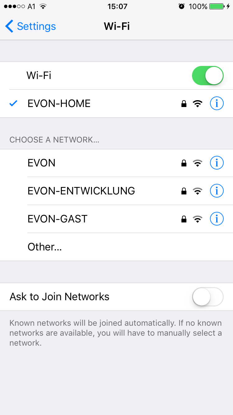
Before your activate your evonHOME app, make sure you are connected to the same network as your evonHOME controller. Simply go to the WLAN settings on your device and check the currently selected WLAN, or connect to the correct one.
In case you switch on your evonHOME CPU for the first time and it does not receive a valid IP address after several attempts (DHCP), it will automatically switch to the following static address:
IP-address: 192.168.50.50
Subnetmask: 255.255.0.0
If you are using the WiFi dongle to connect to evonHOME the controller will always use 192.168.192.1 as its IP address.
Home Screen

Once you have successfully installed the app via the AppStore, the app is located on the home screen. You can start the app directly from here. After a short time to load the app, you will see the start page of the app.
From here, search for the available evonHOME systems. The selection is either a connection via a local Wi-Fi/WLAN or the internet (e.g. mobile network provider via a secure HTTPS connection).
If you are configuring evonHOME for the first time, select “Wi-Fi” in order to search for your system via the local WLAN.
Start Search
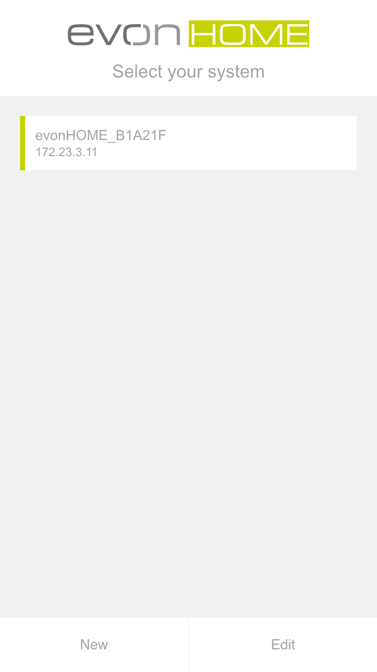
The evonHOME app will now search for all system in your network. As soon as one or more have been found, they will be displayed along with their allocated IP address. Your new system will be listed with the default name evonHOME + unique identification number (e.g. evonHOME_1234AB9). You can change the name later, if your wish.
Once you have selected your evonHOME system, the next thing you must do is login.
Login
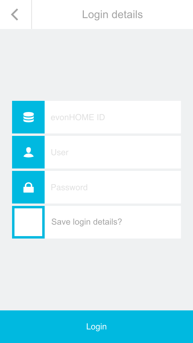
After selecting the evonHOME system, you will find yourself on the login page.
Enter your username and password. You can also determine whether you wish in future to login automatically with your login data.
To make it easier for you to login to your evonHOME on your first configuration, there is also the option to do this by using a QR-code. Use the green button on the top right corner of the login screen to use this feature.
Point the camera at the QR-code, which you will find in your enclosed documents, and position it at the center of the marked area. once the QR-code ist successfully recognized, the associated login field will be filled in.
You have now successfully connected to your evonHOME system and can start to control your home.
To connect for the first time, use the username and password or QR-code provided for you in the enclosed documents.
Browser
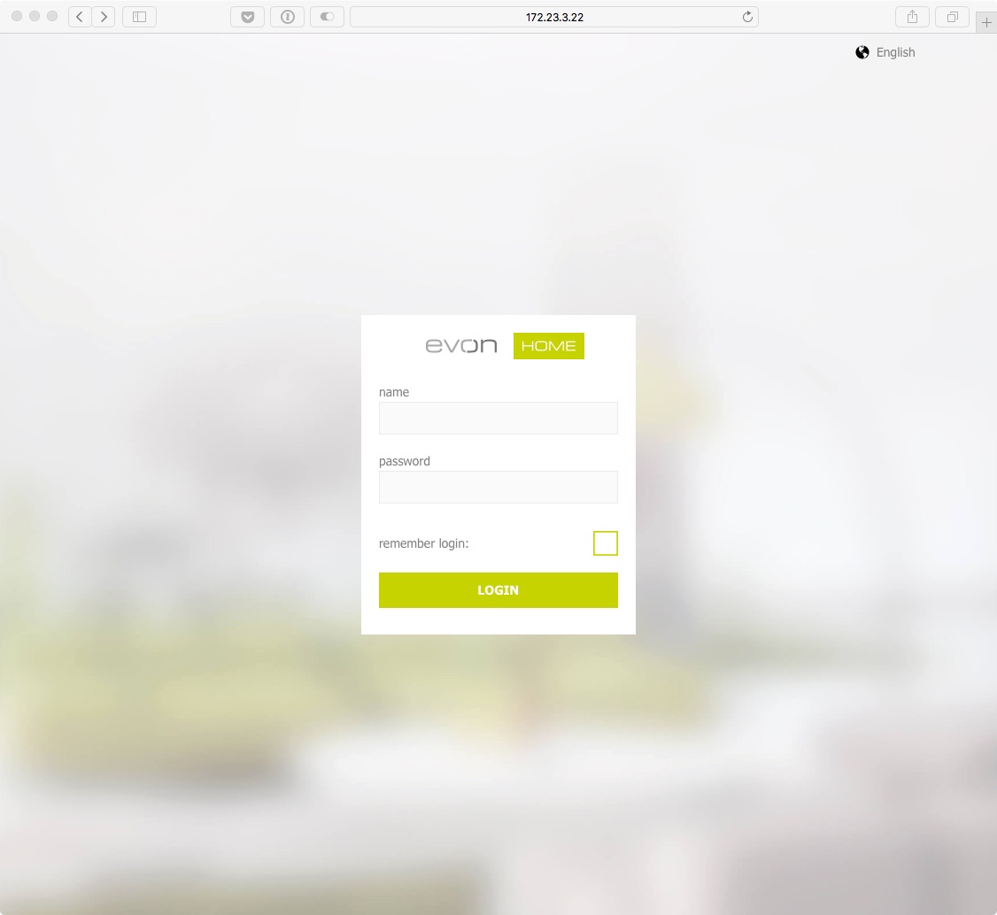
Besides accessing your evonHOME system with the official app, you can also connect to it with any modern browser (e.g. Chrome, Safari, Edge). You only have to know the IP-Adress (Which is displayed in the app once your system is found).
When you enter the address in the url bar of your browser, you will be directed to the login page, where you will have to enter your credentials. You can then use your evonHOME system like you are used to.
If you connect to your evonHOME system with a browser (e.g. Chrome), some device specific functions from the mobile App may not be available to you. These include, among others, native notifications, which also appear when the app is currently not in use.
External Access
If you are currently not at home, but would still like to have access to your home control, then you can use the external access provided by your evonHOME system. If you have activated this option, you can access your system from anywhere in the world assuming there is an Internet connection, just as if you were at home.
The configuration for external access is located under “all apps” – “settings”.
Configuration

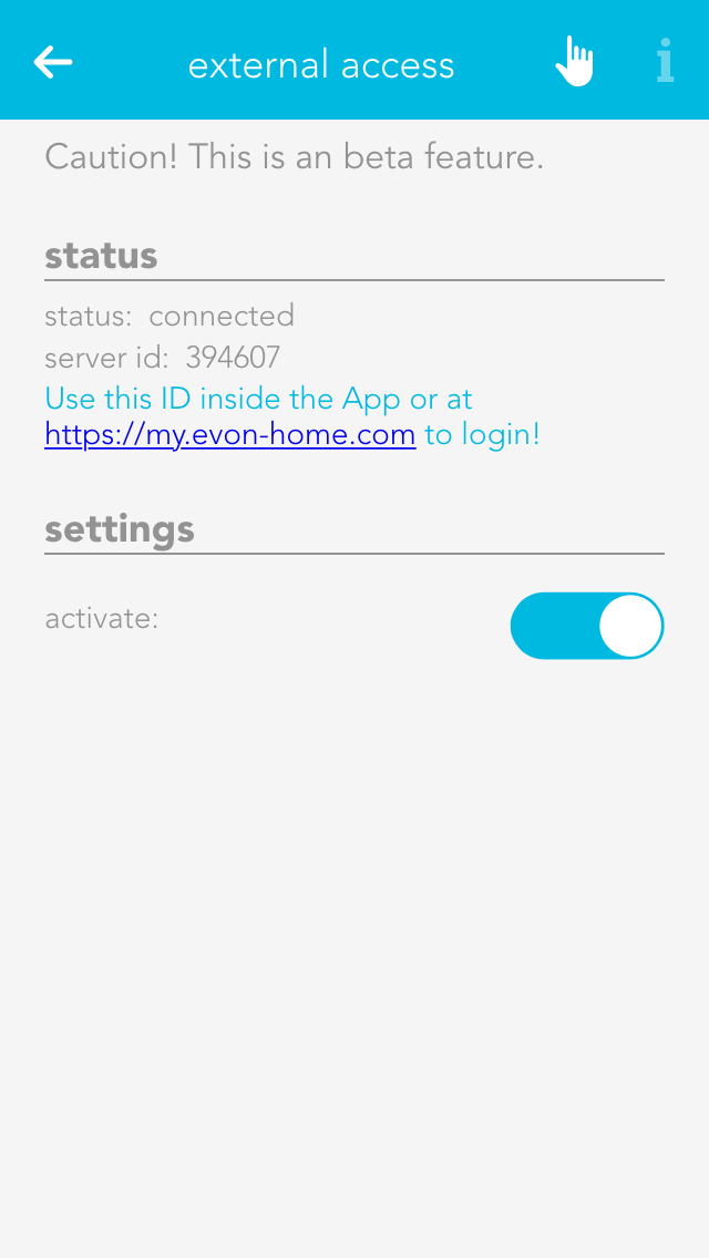
Activate the function for external access in the settings by placing a tick next to it.
As soon as you have activated the function, the displayed status changes from “not connected” to “connected” and the evonHOME ID appears. This ID is required to connect you to your evonHOME system. It is a good idea to write this ID down, you will need it in the next step.
This evonHOME ID gives you the ability to access your system from a normal web browser (via
my.evon-home.com).
Logout

Return to the main screen. On the top left is your current username. If you click on it, the logout button will appear. Logout via this button.
You will now be on the start screen of the evonHOME app, which shows a list of all your previously connected systems.
Connect
Click on “new” to create a new connection. You will now see an overview of all possible connection types, as described previously.
Select “internet” as the connection type. You must enter the evonHOME ID in the next screen, along with your username and password. When done, connect via the button at the bottom of the screen.
As soon as you have successfully connected to your evonHOME system via the external connection, this connection will appear on the start page of your evonHOME app. You can now easily select this connection at any time.
The first external connection to your evonHOME system can take some time. Even once the connection has been established, please wait until all data has been uploaded before your quit the app.
Browser
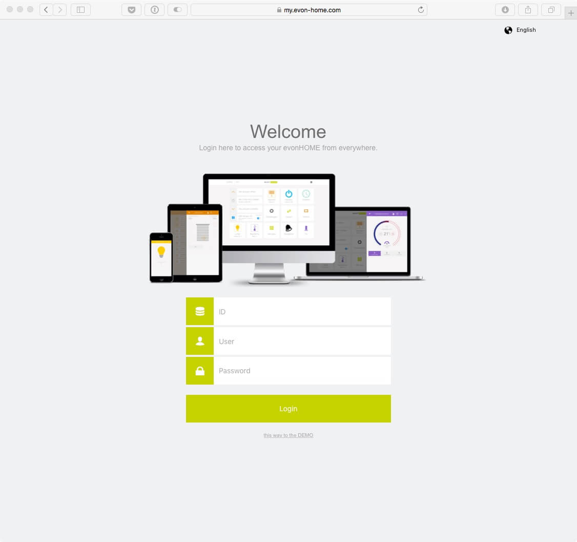
Once you activate the external access, you can connect to your evonHOME system from every supported browser (Safari, Chrome, Edge).
Go to the website my.evon-home.com and login with your credentials. In addition to your user name and password, your will also require the evonHOME ID, which you received by activating the external access.
If you connect to your evonHOME system with a browser (e.g. Chrome), some device specific functions from the mobile App may not be available to you. These include, among others, native notifications, which also appear when the app is currently not in use.
Interface
Visualization of your evonHOME system enables you to control all functions in your home and adjust all necessary settings. There are a few simple concepts that we would like to describe here.
Current User
Once you have logged in, your username is displayed at the top left of the screen. Clicking on your username opens a menu where you can logout.
All Apps
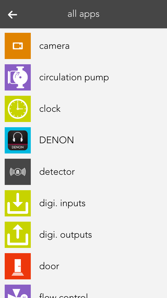
A single click on the symbol (top right) opens all apps. This shows you all available apps. If you don’t want “all apps” open all the time, you can put frequently used apps into your favourites, as follows.
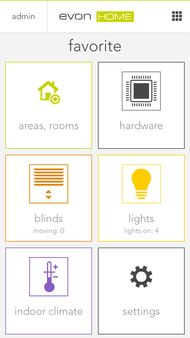
Favorites
Favourites lets you store apps that you use on a frequent basis.
If you want to add something to your favourites, mark the app (press the app with your finger/your cursor until a blue bar appears below) and select “add to start”.
If you want to remove something from your favourites, mark the app and select “remove from start”.
Marked apps can also be moved and sorted.
Areas

After the favourites are your areas. First up are your floors (ground floor and first floor in the diagram) and below that your areas and rooms. However, only those areas that contain something are displayed. For example, if a light is added to the room “bedroom”, the bedroom will be displayed.
Usage
Every app contains different views and representations that are used for opening, operating or changing settings.
App
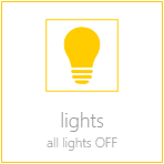
This is the basic representation of every app in the system. A single click/press on this display opens the app view and its functions can be used and/or changed.
App Interface
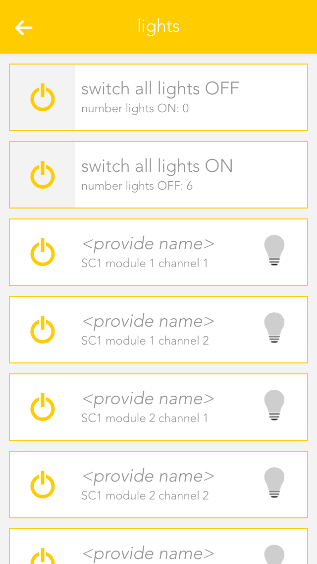
As long as you have an app open, you can also open its view. This shows you all content and functions that are available to you. In the case of the light app, the items displayed include all connected lights and the group functions.
Group Functions
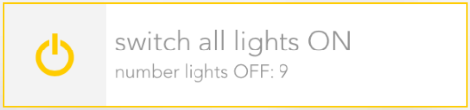
The group function can vary from app to app, but is mainly used to create new elements or to operate several available elements. Taking the app “lights” as an example, it can be used to switch all available lights on or off. In other cases, such as “user”, you can add new users.
Elements
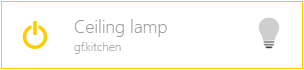
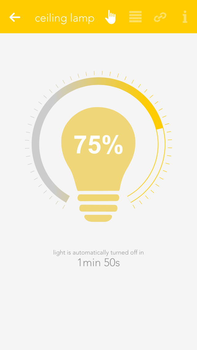
This display represents a single element in the app. In the case of “lights” every single one of your connected lights is displayed like this. The display is divided into several individual sections, each one serving a different purpose. The area on the left contains operating elements in the form of one or more buttons that you can use to control the element (e.g. light on/off). Then there is a text area containing information such as the name and the allocated area. On the right, many apps have a status display showing you the current status of the element. Fo lights, you can see whether the light is on or off, or (if the energy saving mode is active) when the light will be switched off.
Clicking /pressing the text area of an element opens the settings screen where you can change the app name, allocated areas and functions as you wish.
Settings
This display offers you various information and settings possibilities for the selected element and is divided into several sections. On the top right are small buttons that let you jump into other areas. The first section contains the most important operating elements via which you can operate the selected element and, depending on the app, various items of basic information.
The second section contains the settings that you can change for that element. These allow you to change the behaviour of individual element to suit your needs.
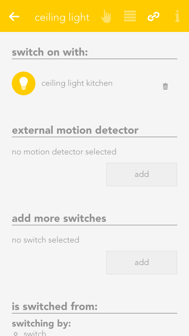
This section shows you al the links for your element. This gives you an overview, should you desire it, of which switches or functions affect the element. You can also link the element with other elements, depending on the app. For example, in the app “lights”, you have the possibility to link a light with a motion sensor.
In the settings view, most of the apps have a button on the top right allowing you to access the official documentation.
Please note that the settings possibilities vary from app to app and therefore not all sections are available for all apps.
Notifications
Your evonHOME uses a range of notifications to inform you of events in the system. For example, if you have integrated a door intercom, the system can notify you when someone rings the doorbell.

Depending on how you access your system, there are different forms of notification. If you access your evonHOME via an app or via a web browser, you will receive new notifications directly in the visualization. All collected and unread notifications can be found via the button “letter symbol” on the main page.
The evonHOME app, used on tablets and mobile phones, also offers you native system notifications. You will receive these even if you are not currently using the evonHOME app.
If you have started the evonHOME app for the first time, you will be asked if you would like to permit notifications to be sent to you. If you agree then the app will be able to send you notifications. You can change the settings for notifications for each individual device that accesses your system later in the app “devices”.
Configuration
Once you have connected the evonHOME app with your evonHOME, there are just a few steps to be taken in order to adapt your evonHOME to your requirements.
Areas
Use the app “areas” to organize your evonHOME into rooms and elements within the rooms (e.g. lights, blinds …). This way, you will be able to find them quickly.

Your previously defined rooms will be displayed on the home screen (as long as they contain elements). To modify the rooms, open the “settings” app and select “areas, rooms”.
Create

In order to add rooms, areas and floors to your evonHOME, simply tap on the corresponding element (e.g. “add room”). This automatically opens the operator panel for the added element. Enter the name into the field “name” and an abbreviation in the field “abbreviation” for the room. If you want to allocate this new room to a floor, simply select the floor you want. If you want to move the area back to the highest level, select the empty entry in “area, floors”.
Alternatively you can first navigate to a floor and add a room there.
Settings

If you wish to personalize your rooms, you can select colour, icon and background picture for your room. Do this by opening the operator panel for the room via in “settings” – “areas, rooms” and select the element under “settings” and modify it.
Open the area via the button “edit” and view the elements for this area. If you want a shortcut to an area, simply click on the area of the symbol in the object panel (left).
You can also link each room with a room thermostat. Do this by allocating an element to this room in the app room climate. If you have allocated more than one room thermostat to a room, you can use the parameter panel of the room to select the room thermostat you wish to use for the room temperature display.
Naming
After you have connected via the evonHOME app to your evonHOME system, you should name all of the connected devices (lights, blinds, heating circuits, etc.) and allocate them to a room. This helps you to not only find and operate them easier, but also to access further functions.
Select

Open “lights”, “blinds” or “room climate”, depending on the items you wish to modify the names and rooms.
The app shows you a list of central functions and below that a list of your elements – this corresponds to the channels of your evonHOME modules. More detail concerning the central functions can be found in the corresponding documentation.
Tap on the area that displays the name and the room, in this case “ no name”, “no room” to open the settings for this device.
Provide Name and Room

Enter the name of the device in the field “name”. You can type any name in here, or use a predefined name by tapping on the small arrow.
Tap on the field to select a room. The system already has a predefined few names that you can use. If you cannot find a suitable room in the list, create one in the settings -> areas and custom rooms.
You do not need to specifically save your changes, simply tap on the arrow symbol in the menu bar.
Choose a distinctive name depending on the device and purpose like: ceiling light, ambient, radiator or wall heating.
User & Groups
You can allocate different rights in your evonHOME to users, for example so that children can only use functions in the children’s room. The rights are controlled via the user groups.

You can find users and user groups in “all apps” – “settings”.
User
A user allows you to control exactly the rights for your evonHOME.
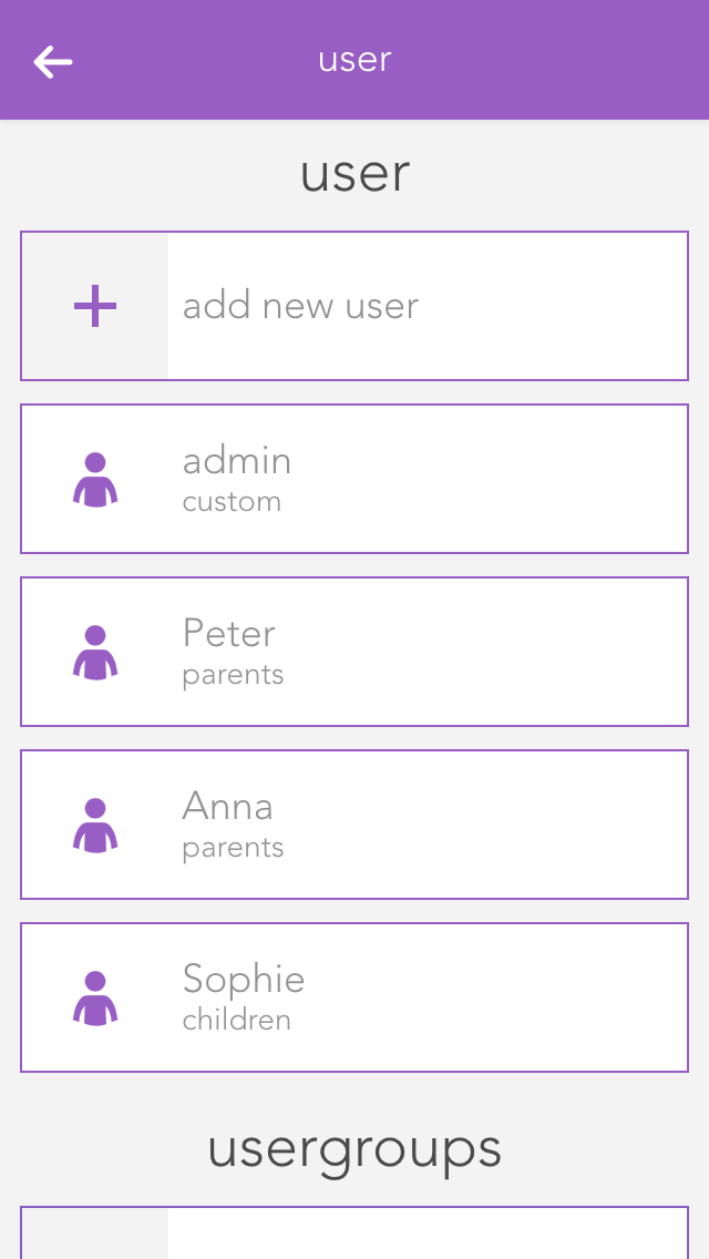
You can add a new user here or configure an existing one. To add a new user, simply select “add user”. This opens a panel where you can enter the user name and an optional description. Enter a password for the user so that you can login using the username.
Settings

Profile picture
The profile picture to be displayed for this user.
Background picture and text colour
You change the background of your visualization as you wish. The text colour selects the colour of titles such as “favourites” on the home screen so that they are readable, even with other background pictures.
Show areas on the home screen
This setting lets you define whether areas will be displayed on this user’s home screen.
Own favourites
If you activate the option “own favourites”, you can customize the favourites on your own home screen without these changes being visible to other users. If this option is deactivated, then your favourites are shared with other users and any changes will be visible to all users.
Language
This lets you change the language for this user. To change the language of the current user, click on “load new language settings”.
Permissions
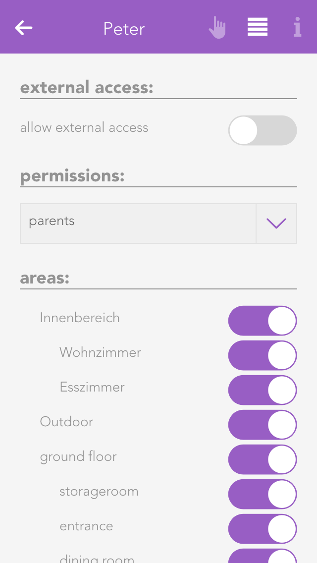
Permit external access
The option “allow external access” lets you decide whether this user is permitted to connect to your evonHOME externally.
Rights
This allows you to allocate rights to this user. If you want to allocate rights independently from a group, simply select “user defined”. The individual rights are explained further down the screen. If the user is to have no rights, simply select “no rights”.
Areas
The section “areas” lets you select which the areas this user is to have access to. If you have allocated this user to a user group, the rights in this group have already been defined for this area and hence you only have the possibility to limit the rights for individual areas further.
Some changes cannot be made to the user you have used for your login. So for example you cannot withdraw administrator rights or delete the current user.
Groups
User groups allow you to configure rights for several users.

The settings can be modified for a user group that already exists, or a new one can be created. To create a new user group, click on the element “add group”. This opens a panel where you can enter the name of the group (e.g. “guests”), and assign colour and an icon.
Permissions
Rights are used to limit what a user in this group is allowed to do in your evonHOME.

Admin
This level of rights gives the user full access to all possibilities in the system. All the following rights are deactivated, since they are all included in the admin rights.
Change parameter
Users in this group are allowed to change parameters, i.e. all settings accessible via the parameter symbol.
Manage settings
The user can open the settings (all apps – settings) and make changes. Exceptions are the user settings.
Manage home screen
The user can change the start page of the app, in other words, they can set favourites and move elements. See also “own home screen”.
Add object
The user can add new objects to the system, for example a new surveillance camera, a new Denon system, etc.
Edit logic
The user can create and edit logic elements.
Edit scenes
The user can create and edit scenes; otherwise scenes can only be executed.
Edit area
The user can create and edit areas.
Execute universal scene
The user can execute universal scenes such as close all blinds, switch on all lights, etc.
See all apps
The user can open all apps, otherwise they only have the possibility to open apps that are on the home screen.
See notifications
Notifications are displayed for the user (such as wind, alarm system, etc.).
Areas

In “areas”, you can define which areas the users in the group will be able to access.
Light
A light in evonHOME corresponds to a lighting channel that is connected to an evonHOME light module. Once connected, each light can be switched on and off. In addition, you also have the pre-defined universal functions “all lights on” and “all lights off”.

You can find the lights under “all apps”.
Usage

You can switch a light on or off via the “power symbol” on the left side. The right-hand side of the panel shows you whether the light is currently switched on or off. Clicking on the element takes you into the extended operation or configuration of this light. You can switch the light on or off by clicking on the bulb symbol.

If you have a dimmable light, you can switch in on or off via the object panel. Of course, you can also control this dimmable light via the operator panel by setting the circular slider around the light to the desired value.
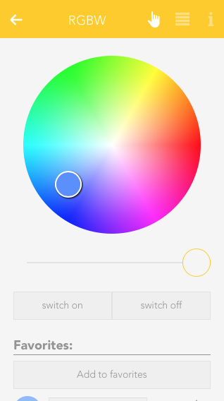
RGBW
If you own a RGBW Module (HC-L1644), you can control the desired light color and brightness from within the OperatorPanel.

Additionally, you can also save the current light settings as a favorite and activate it again later.

Saved favorites will also be displayed in the ObjectPanel, if you resize it to the appropriate size.
Configuration
Once a light has been given a name, you can configure it to suit your needs.
General

Mode
This setting determines whether this light is controlled by a switch or a presence detector. If you select “presence detector”, the settings to adjust the time the light is switched on are displayed.
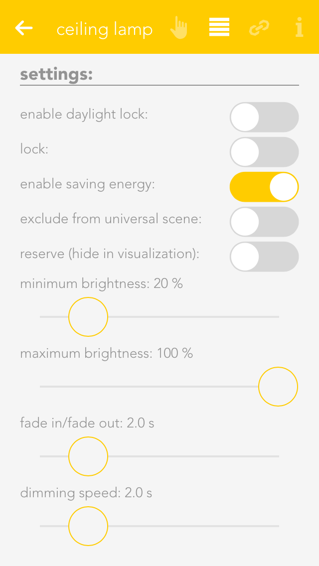
Activate daylight lock
This option lets you prevent the light from switching on during the day (if there is sufficient light). This can be used for a hallway where the light is controlled by a presence detector. You can adjust the source for daylight detection in the global settings.
Lock
If you activate “lock”, then the light cannot be switched on or off by the switch, nor by the presence detector.
Activate energy saving mode
This option lets you configure the light to switch itself off after a certain time. If you have activated this option, then the software shows you the settings for the time the light is to remain switched on. You can change this time to anything you want.
Remove from universal scene
An example of a universal scene is “all lights off”, where all lights are switched off. However, if you want a particular light to be excepted from this, then activate this option (useful for lighting an aquarium).
Reserve
If you have a module with spare connections, i.e. where no light is connected, the app still shows that the light is on or off, because the output is active (although no light is actually connected). The “reserve” field lets you hide lights that are not used/connected. You can reactivate this light via the corresponding module in the app “hardware”.
Dimmer

Minimum and maximum brightness
Minimum and maximum brightness: many lights only have a noticeable change in brightness within a certain range. Hence you can set a minimum and maximum brightness level so that dimming will happen in between those limits. The visualization will still display 0% to 100%.
Fade in time
This is the time that the light is to take to reach the desired brightness from being switched off.
Dim speed
This is how fast the brightness is reached when the button is pressed continuously.
RGBW

Minimum brightness
Legt die kleinste Helligkeitsstufe fest
Set the minimum brightness level
Maximum brightness
Set the maximum brightness level
Fading time
This will set the time it takes for the light to dimm between "on" and "off" state rather than switching instantly.

Dimm speed
Sets the time it takes for the light to dimm to the desired brightness.
Color changing speed
This setting will affect how fast the light switches through all available colors when using the linked switch with a longpress.
Only white
When this setting is active, the color wheel will be hidden and only the brightness slider is available in the OperatorPanel.
Enable saving energy
Enables the energy saving mode, in which the light will switch itself off after a given time. You can adjust the desired time with the given interface elements, which appear once this setting is active.
Exclude from universal scene
Activating this option will exclude it from Universal scenes which will not impact this light anymore until this option is turned off.
Switch off automatically after
This option only appears after the "enable saving energy" setting it active. It allows you to adjust the time it takes for the light to switch itself off.
While the standard mode of the RGBW Module is "1xRGBW" it is also possible to switch to "4xWhite". This will allow you to connect 4 separate lights to one RGBW module and use them like normal dimmable lights. To change this setting, go to "All apps" - "Hardware" and navigate to the correct module ("Light1644"). Click on the Name and change the setting in the appearing OperatorPanel.
Settings
You can configure settings that affect all lights in “all apps – settings – lights”.
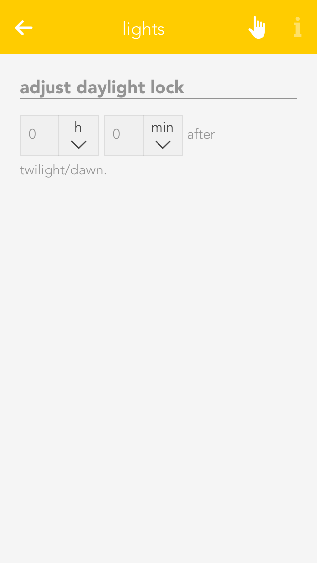
Daylight-lock-delayed switching
To configure the daylight lock, navigate to settings and select lights. You can adjust how many minutes after dusk you want the daylight lock to be deactivated and how many minutes after dawn you wish the daylight lock to be activated. In other words, if your evonHOME registers dusk at 8pm and you have set 10 minutes, then the daylight lock will be deactivated at 8:10pm.
Examples
You can find possible application examples here:
Blind
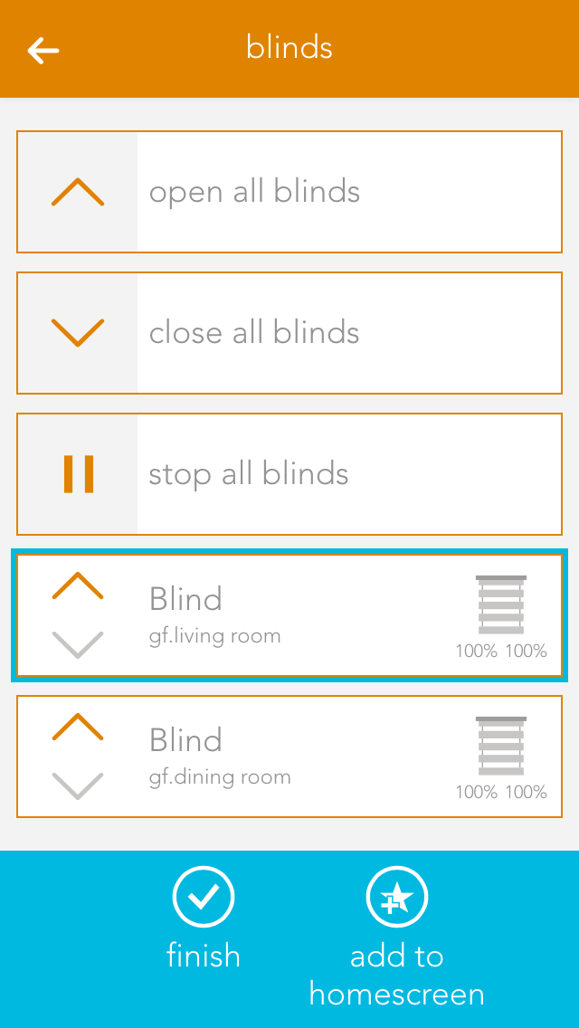
The app “Blinds” lets you operate and configure all shading elements in your system. You also have pre-defined functions such as “open all blinds” and “close all blinds”.
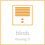
You can find Blinds under “all apps”.
Usage

You can open or close your shading element using the arrows in the left-hand side of the object panel. The right-hand side of the panel shows the current position and the angle of the blinds.

You can also operate each blind element via the operator panel by using the sliders on the right and on the left, or dragging the point in the middle of this window to the desired position. If you have defined a favourite position and wish to use it, simply click on the button “go to favourite position”.
Szenen
Die Beschattung bietet folgende Funktionen für evonHOME Szenen (Dann...):
- Alle auf Favoriten Position fahren: Alle Beschattungselemente werden auf die jeweils eingestellte Favoriten-Position gefahren
- Alle auf Position fahren: Alle Beschattungselemente werden auf eine frei definierbare Position und einen frei definierbaren Lamellen-Winkel gefahren
Der Beschattung bietet folgende Funktionen für evonHOME Szenen (Dann...): Alle Beschattungselemente werden auf einen frei definierbaren Winkel gestellt - Alle stoppen: Alle Beschattungselemente werden gestoppt
- Alle öffnen: Alle Beschattungselemente werden geöffnet
- Alle schließen: Alle Beschattungselemente werden geschlossen
- Auf Favoriten Position fahren: Das Beschattungselement wird auf die definierte Favoritenposition gefahren.
- Auf Position fahren: Das Beschattungselement wird auf eine frei wählbare Position und einen frei wählbaren Lamellen-Winkel gefahren
- Auf Winkel stellen: Das Beschattungselement wird auf einen frei wählbaren Lamellen-Winkel gefahren
- Öffnen: Das Beschattungselement wird vollständig geöffnet
- Schließen: Das Beschattungselement wird vollständig geschlossen
- Stoppen: Das Beschattungselement wird gestoppt.
Beschattungselemente können unter den Einstellungen von Universalszenen ausgenommen werden. Für ausgenommene Elemente werden die Szenen-Funktionen "Alle..." nicht angewendet.
Configuration
Apart from giving the shading elements individual names, you can customize them further to suit your needs.
Settings

Mode
This option is available when an 'evonHOME Blind 1344' (Schlotterer RETROLux) module is used. It allows to change the operation mode from 'standard blind' to 'without working position' or 'with working position'. In this case, 'working position' refers to a blind with a mechanical working position.
With working position
This mode is meant for use with the Schlotterer RETROLux venetian blind, which has a mechanical working position. It allows you to change the slat position with a short button press and to switch between 'closed' and 'working position'. In this mode, the slats can only be adjusted to a certain limit, which is caused by the underlying mechanical construction of these blinds.
Without working position
Choose this mode if you own a Schlotterer RETROLux venetian blind, which does not not have a working position. This mode grants you the ability to simulate a working position.
Type
Type lets you select whether the blind is a jalousie, a rolling shutter or a window (windows will be dealt with in an extra chapter). The jalousie has a position, an angle of the slats and a turnaround time, all of which must be considered in the calculation. A rolling shutter does not have an angle.
Vertical jalousie
If you have a jalousie that opens and closes vertically, then you can configure it here. If this is activated, you are then presented with a further option defining the direction you wish the jalousie to open.
Remove from universal scene
A universal scene could be “open all blinds”. However, if you want this shading element to be excepted from this universal scene, then activate this option.
Remove from wind-lock
If you do not want this blind to open in strong wind, then activate this option. If this option is not visible, then activate the wind-lock in the settings “all-apps – settings – shading”.
Lock blind
Use this option to lock a blind, which means that the shading position can no longer be changed via the app or the button.
Close at dusk
If you want the shade to close at dusk, then activate this option.
Reserve
If you have a module that has reserve connections, i.e. blinds are not connected to every output, then these elements are still displayed. The reserve function allows you to hide unused shading elements in the app. If you wish to see these unused elements, activate them in the corresponding module in the hardware section.

Extended parameter
If you use the 'evonHOME Blind 1344' module in combination with a Schlotterer venetian blind (and select the correct operation mode) additional options will be available to you here.
Those refer to the varied motion times, which are specific to Schlotterer blinds, like working position/snapping times. This settings are pre configured for optimal operation. In case you encounter any problems when switching between positions (working mode/closed) please contact your evonHOME partner, who can adjust those settings for you.
Travel Times
Travel time wizard
This wizard lets you easily and simply determine the travel times for your shading element. Simply follow the instructions and your travel times will be configured for you.
Use these travel times for all blinds
Pressing this button opens a dialog where you can have all blinds use these travel times. This is useful if all blinds are of the same type and you do not wish to have individual times for each blind.
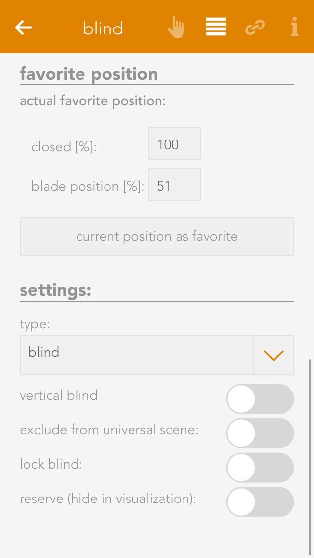
Favorite Position

You can save your favourite blind position either by entering the values by hand or pressing the button “use current position as favourite”. The favourite position can be triggered via a scene.
Linking
Linking allows you to connect your shading elements to other elements in your evonHOME.
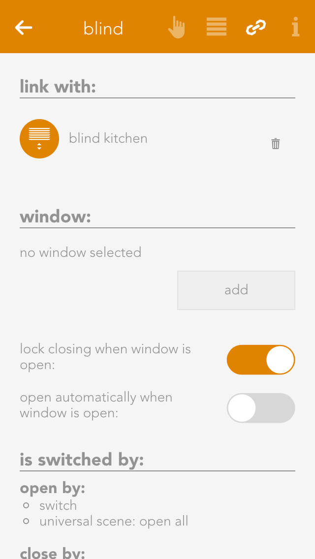
Connect with
If you want two shading elements to always have the same position and slat angle, then use this “connect with”. Navigate to “connect with” and press “select” to choose the shading element you wish to connect to.
Gruppenfunktion
Über die Gruppenfunktion lassen sich mehrere Beschattungen zu einer Gruppe zusammenfassen. Dadurch werden alle gleichzeitig geschalten.

Um eine neue Beschattungsgruppe anzulegen, wähle "Neue Beschattungsgruppe" innerhalb der Beschattungs App.

Eine neue Beschattungsgruppe wird erstellt.

In den Einstellungen der Gruppe solltest Du als erstes einen Namen vergeben und einen Raum zuordnen.
Hier hast Du außerdem die Möglichkeit, die Gruppe zu deaktivieren. Dadurch kannst du eine bereits konfigurierte Gruppe temporär abschalten, ohne sie löschen zu müssen.

Füge nun mehrere Beschattungen hinzu. Alle Beschattungen die sich in der Gruppe befinden werden nun gleichzeitig geschalten. Schließt Du eine Beschattung der Gruppe, werden auch alle anderen geschlossen. In den Einstellungen hast Du außerdem die Möglichkeit die "Starre Kopplung" zu deaktivieren. Ist diese Funktion aktiv, fahren alle Beschattungen immer auf die selbe Zielposition und nehmen dadurch am Ende die gleiche Stellung ein. Ist sie deaktiviert, reagieren die Beschattungen nur noch auf "Auf" und "Zu" Gruppenbefehle oder auf die Befehle der verknüpften Taster in der Gruppe. Dadurch bewegen sie sich gleichzeitig, können aber dabei unterschiedliche Positionen haben.
Die Gruppenfunktion wirkt sich sowohl auf die Bedienung über die evonHOME Visualisierung, als auch Taster aus. Du kannst außerdem zu jeder Gruppe weitere Taster hinzufügen.
Settings
Settings contains the configuration for general settings that are valid for all shading element. Navigate to “all apps – settings – blinds”.

Mode
Short button press – completely up: If the blinds button is pressed for a short period of time, then the blinds will travel in the desired direction until either the blinds are fully open/closed, or a further press of the button causes them to stop where they are. A long button press sets the angle for the slats, i.e. after a wait time to correctly identify a long button press, the blind slats begin to turn until the button is released.
Short button press - set slats: A short button press changes the angle of the blinds and a long button press completely opens or closes the jalousie. A second button press interrupts the travel and the jalousie stops where it is.
Over-travel time
The over-travel time lets you define the percent of time to increase the time that the jalousie takes for completely UP to completely DOWN. This makes sure that the blinds are really open or closed.
Activate wind lock
If you have activated this option, then all shading elements are closed if it is windy. If you want to exempt elements from this wind lock, it can be done for each individual element.
Close at twilight
If “close at twilight” is selected, then all blinds will close as soon as twilight is detected. If you do not want all blinds to close at twilight, then deactivate “close at twilight” for each individual blind. In addition, you can also delay the closing at twilight by entering the number of minutes you wish to wait after twilight until the blinds close.
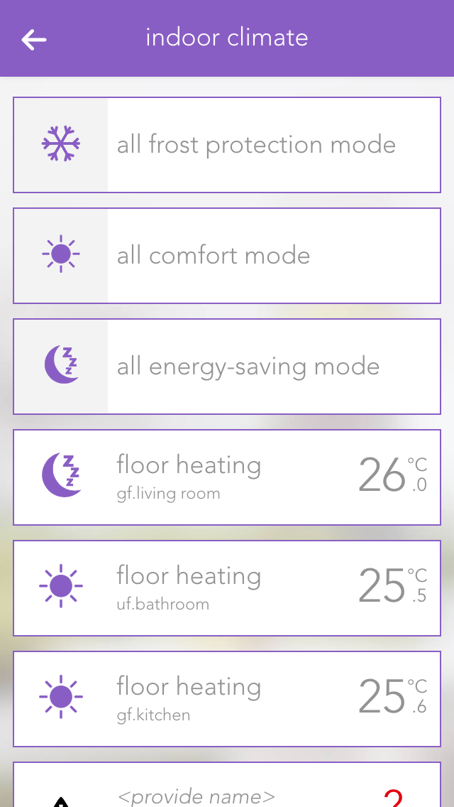
Indoor climate
The app “indoor climate” lets you operate and configure all room climate elements in your system. You also have the pre-defined central functions “all frost protection mode”, “all comfort mode” and “all energy saving mode”.

The app is located under “all apps” – “indoor climate”.
Usage
Clicking on the left-hand area of the object panel switches back and forth between comfort mode and energy saving mode.

You can also select the operating mode using the three buttons located next to each other in the operator panel. The desired temperature can be adjusted in the circle above these buttons via the “+” and “-“ buttons, or you can simply click on the position in the circle that you want.
Configuration
General

Deactivate individual room control
If you have a module type C1144, you can deactivate a connected room control panel with this setting. In this case, only the actual value is taken from the room control panel. All other values are ignored.
External actual value
If you have a module type C1244, you can activate this setting to receive the actual value from another source than a connected PT1000. If you use this setting, you will have to choose the new source in the linkpanel.
Cooling disabled
This setting allows you to deactivate cooling for the connected climate device. Additionally, while this option is active, the cooling mode from the global settings will also be ignored.
Permanent ON/OFF
The valve output can be permanently switched on or off, independently of the current temperature and the current operating mode.
Remove from universal scene
The valve output can be permanently switched on or off, independently of the current temperature and the current operating mode.
Display actual/desired value
This value determines whether the actual or desired value should be displayed in the object panel.
Reserve
Even if not all room climate channels are connected to a module, all four control elements are still displayed for this module. If you want to hide these unconnected control elements, then mark them as reserved. You can unhide them via the app “hardware” (all apps – “hardware”).
Setpoints

The desired values for the various operating modes are defined here. Clicking on the button “use this desired value for the entire room climate” opens up a dialogue with which the desired values in this room climate element can also be used for all other elements.
Presence Rise

If the presence button on the room control panel is pressed, the desired temperature of the room is increased by the defined value and time period.
Temperature Limit

The item “temperature limit” lets you define a temperature limit, i.e. you can react with a scene if the value falls below or exceeds the limit. You can also activate notifications for falling below or exceeding the limit via “notifications for temperature limits”.
Linking
Links allow you to connect your room climate with other elements in your evonHOME.

Window contact
To ensure that heating is suspended when a window is open, you can add as many windows as you want via the button “add”. If one of these windows is opened, the heating will automatically enter into frost protection mode. As soon as the window is closed, comfort mode will be reactivated.
Settings
The settings for all room climate elements can be found under “all apps” –“settings” – “indoor climate”.

Can cool
If your heating system supports cooling, then you can activate this option. Warning! If your heating is not suitable for cooling, using this option could lead to malfunction. If in doubt, please contact a heating specialist.
Szenen
Das Raumklima bietet folgende Funktionen für evonHOME Szenen (Dann...):
- Auf Energiesparen umschalten: Der Status Energiesparen wird für den Heiz -/Kühlkreis aktiv und die Sollwerte für Energiesparen werden angewendet
- Auf Frostschutz umschalten: Der Status Frostschutz wird für den Heiz -/Kühlkreis aktiv und die Sollwerte für Frostschutz werden angewendet
- Auf Komfortbetrieb umschalten: Der Status Komfortbetrieb wird für den Heiz -/Kühlkreis aktiv und die Sollwerte für Komfortbetrieb werden angewendet
In- and Outputs
A few inputs and outputs in evonHOME are used similarly in different modules. This is described in this section.
Switches
A switch can be connected to a light module, blind module or a digital module. A switch has a pre-defined function for a light or blind module. Every switch can be simulated in evonHOME for test purposes.

These switches can be found under “all apps” – “switches”.
Configuration

Naming
If you have connected your switch to a light or shading module, then the switch is automatically named according to the light or blind. If you wish to give it a different name, then deactivate the option “same name as blind/light” in the parameter panel and give the switch a new name. If you have connected your switch to a digital module, then you must name it yourself.
Reserve
If you have a switch in your system that you don’t use, then you can hide it by deactivating the option “reserve “hide in display” in the app “ switches”. To unhide it, you can find your switch in the app “hardware”.
Mode
If you want to change the mode, i.e. define the switch as a presence detector or a digital input, then you can do this in the parameter panel under “mode”. Not every module can change the mode however, or not all possibilities are available. This means that the light modules’ switch can only be converted to a presence detector. Switches for a blind element cannot be converted. Switches for digital modules have all three modes.
Simulation

If you have linked a switch to a scene and would now like to simulate this scene, then there is no need to go to the switch and press it every time, you can use simulation to create the switch press. Simply activate the option “simulation” in the operator panel to see 3 buttons that you can use to simulate switch presses.
Warning: If you leave the simulation mode activated, the autonomous functions will not work!
Scene

You can use the switches for a scene (assuming it as been named). In the scene “if …” just select the switch and decide if you want the scene to be executed after a single, double or long press.
Settings
Open the switches settings (“all apps” – “settings” – “switches”) if you want to define the times for a press and double-press. Select the desired values and confirm them by clicking the button “use values for all switches”.

Hold time (long button press)
A switch must be pressed for at least thus time to be recognized as a long button press.
Wait time (double-press)
The gap between two switch presses must be as least as big as the defined wait time to be recognized as a double-press.
If you wish to define different values for a switch that is connected to a blind module, then activate the option “use other values for blinds”.
Motion Detector
A motion detector can be connected to a light module or a digital module. The motion detector has a pre-defined function when connected to a light module. Motion detectors can be simulated in evonHOME for test purposes.

You can find motion detectors under “all apps” –“motion detectors”.
Configuration

Naming
If you have connected a motion detector to a light module, then it is automatically assigned the same name as the light. If you wish to assign a different name, then deactivate the option “same name as light” in the parameter panel and enter the name you wish. If the motion detector is connected to a digital module, then you must assign it a name yourself.
Invert
If the motion detector is connected to a digital module, you have the possibility to invert the logic by activating the option “invert” in the operator panel.
Reserve
Should you have a motion detector in the system that you do not use, you can hide in from the app “motion detector” by activating the option “reserve (hide in display)” in the parameter panel. To unhide it, you will find your movement detector in the app “hardware”.
Mode
If you wish to change the mode, i.e. convert the motion detector input to a switch or a digital input, you can do this by changing the mode for the motion detector in the parameter panel. Not all modes can be changed in all modules, or not all possibilities are available. This means that a motion detector for a light module can only be changed into a button. All three modes are available for motion detectors for a digital module.
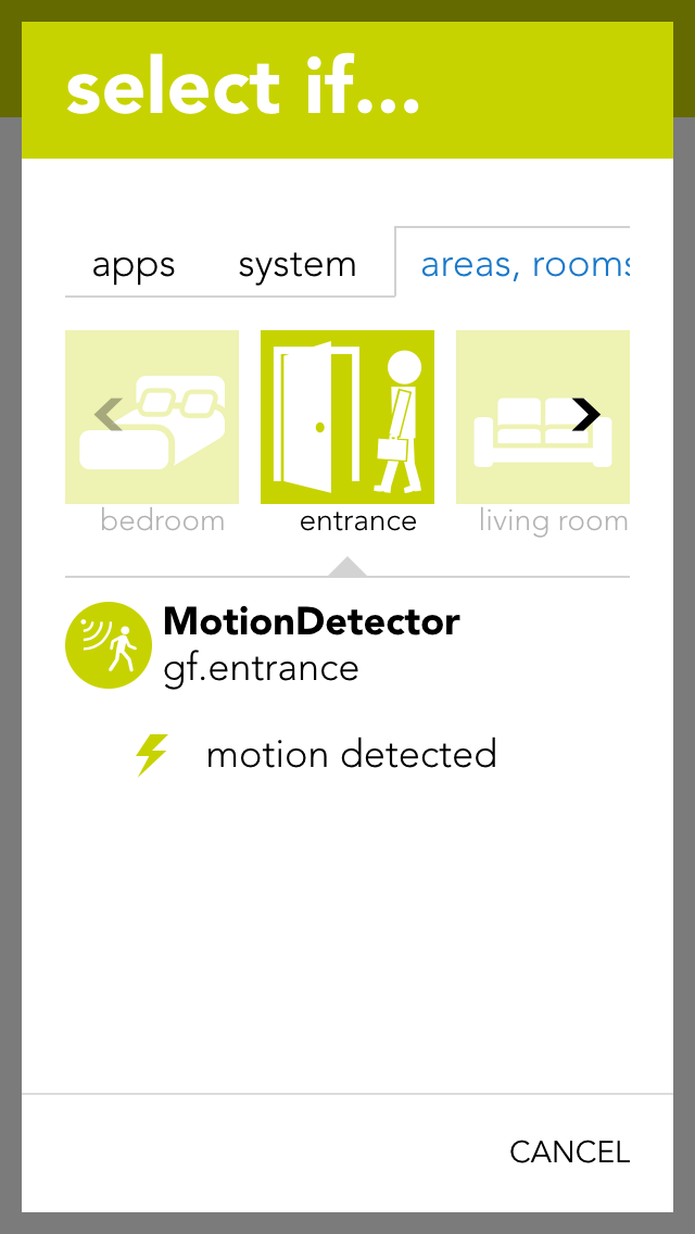
Scenes
You can also use the motion detector for a scene (in as far as it has been named). In the scene, select the motion detector for “if …” and decide if you want the scene to be carried out on the rising or falling edge of the signal.
Rising edge
The electrical contact of the motion detector has been activated.
Falling edge
The electrical contact of the motion detector has been deactivated (after the internal time of the motion detector).
Simulation

For example, if you have linked a motion detector to a scene and you would like to test this scene, then you do not have to go to the motion detector and activate it every time, you can change the state using simulation. Simply activate the option “simulation on” in the operator panel to see the option with which you can change the state.
Warning, if you leave the simulation switched on, the autonomous function will not work!
Digital Input
You can use a digital input for functions not provided by any evonHOME function module. You can name each digital input and simulate then for test purposes.

You can find the app “digital inputs” under “all apps” – “digital inputs”.
Configuration

Reserve
If you have a digital input in your system that you are not using, you can activate the option “reserve (hide in visualization) to hide this digital input in the app “digital inputs”. (To unhide this, the digital input can be found in the hardware app)
Mode
If you wish to change the mode, i.e. convert a digital input into a button or a movement detector, this can be done in the parameter panel for the digital input under “mode”.
Simulation

If you have connected a digital input to a scene and would like to test the scene, you do not have to navigate to the digital input and activate it every time, you can change it directly via simulation. To do this, activate “simulation on” in the operator panel to see the option “simulation value” with which you can change the state. Warning, once the simulation has been activated, the autonomous function will no longer work! Any changes in the state of the input “hardware” will be overwritten by the simulation.
Scenes
You can also use a digital input for a scene (in as far as it has been named). Select the digital input in the scene’s “IF ….” and decide whether you want the scene to be carried out on the rising or falling edge.
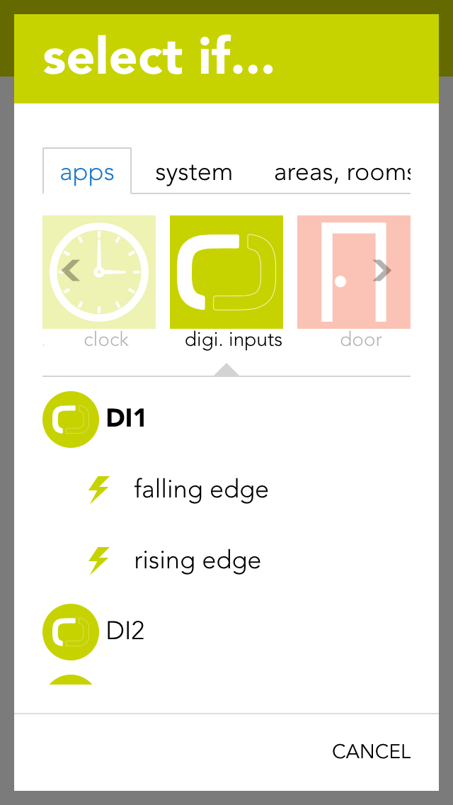
Rising edge
The electrical contact of the digital input has been closed.
Falling edge
The electrical contact of the digital input has been opened.
Digital Output
The app “digital outputs” provides you with an overview of all digital outputs in your system. This is where you can name them and change the state of the outputs.

The app “digital outputs” is located under “all apps” – “digital outputs”.
You have two possibilities to change the state of a digital output. Either you can click on the power symbol on the left in the object panel or you can click on the button “switch” in the operator panel.
Configuration
You can give a name to a digital output in the parameter panel and optionally allocate it to a room.

Save output if bus fault
If the output is active when the bus connection to the CPU fails (for example if the 24V power supply to the module fails), this option lets you guarantee that the active remains activated even in a fail state. If this option is not activated, then the output is reset after every bus connection failure.
In safety-critical controllers, it should be carefully examined whether this function should be activated, since this output is kept active if the system fails.
Mode
With the mode setting, you can change the behavior of the output once it is active. The following options exist:
-
Standard
This ist the normal setting for a digital output. With this, the output stays active until the signal ends. -
Minimum on duration
With this mode, the output stays active for at least the specified time, even when it is deactivated before. -
Pulse
In this mode, the output will automatically be deactivated after the defined timeframe.
Reserve (hide in visualization)
If you have a digital output in your system that you do not use, then you can hide this digital output in the digital output app by activating the option “reserve (hide in visualization)” (located in the parameter panel). (To unhide, the digital output can be found in the hardware app).
Change mode
If you wish to change the mode, i.e. convert a digital output to a socket, then you can do this by changing the mode for the digital output in the parameter panel.
Scenes
You can also use a digital output for a scene (in as far as it has been named). In the scene’s “if …” simply select the digital output to see the following possibilities:

Switch off
The digital output is switched off.
Switch on
The digital output is switched on.
switch on for
The digital output will be switched on for a defined amount of time.
Toggle
The state of the digital output is toggled.
Socket
The app “sockets” provides an overview of all sockets in your system and allows you to name them and change their state.
The app “sockets” can be found under “all apps” – “sockets”.
You have two possibilities to change the state of a socket. Either you can click on the power symbol on the left in the object panel or you can click on the button “toggle” in the operator panel.
Configuration
The parameter panel lets you give the socket a name and optionally allocate it to a room.

Save output if bus fault
If the socket is currently active and the bus connection to the CPU fails (e.g. the 24V power supply to the module fails), then activating this option will guarantee that the socket remains active even in a fail state. If this option is not activated, then the socket is reset after every bus connection failure.
In safety-critical controllers, it should be carefully examined whether this function should be activated, since this output is kept active if the system fails.
Reserve (hide in visualization)
If you have a socket in your system that you do not user, you can hide this socket in the app “sockets” by activating the option “reserve (hide in visualization) (located in the parameter panel). (To unhide, the socket can be found in the app “hardware”).
Change mode
If you want to change the mode, i.e. convert socket to a digital output, then this can be done by changing the mode in the socket’s parameter panel.
Scenes
The socket can be used for a scene (in as far as it has been named). In the scene’s “if….”, select the socket and one of the following possibilities:

Switch off
The socket is switched off.
Switch on
The socket is switched on.
Switch on for
The socket is switched on for the time you define.
Toggle
The status of the socket is toggled.
Analog Input
An analog input can measure voltage in the range 0-10V. This voltage is then scaled to the range defined by the user. This value can be used by the user for calculations (using logic), or simply to trigger scenes if the value exceeds or falls below certain (definable) limits.

The analog inputs are located under “all apps” – “analog inputs”.
Configuration

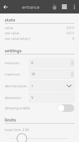
Minimum/Maximum
Minimum and maximum limits of the measured value. These inputs must be taken from the description of the sensor used. For example, you wish to measure the humidity in a room and use a sensor with a 0-10V output signal. The sensor documentation tells you that the sensor can measure humidity from 0% to 100%. The minimum limit is hence 0 and the maximum limit is 100.
Number of decimal places
Indicates the number of decimal places used to calculate the value.
Dimension
This is where you define exactly what you wish to measure with this analog input (e.g. temperature °C).
Notification on limit violation
If the value of the analog input falls below the lower limit or exceeds the upper limit, then you will be notified by the system if this checkbox is activated.
Upper limit
Enter the upper limit here. If the value exceed this limit, you can react with a scene by selecting the trigger for “value above upper limit” in the “IF …” statement.
Lower limit
Enter the lower limit here. If the value falls below this limit, you can react with a scene by selecting the trigger for “value below upper limit” in the “IF …” statement.
Szenen
Der Analoge Eingang bietet folgende Auslöser für evonHOME Szenen (Wenn...):
- Obere Grenze wurde überschritten: Die parametrierte obere Grenze wurde vom Messwert überschritten
- Untere Grenze wurde unterschritten: Die parametrierte untere Grenze wurde vom Messwert unterschritten
Data Description
Raw value
A raw value is the voltage (0-10V) measured on the input of the module.
Raw value (phys.)
Corresponds to the output of an analog/digital converter and is used for the calculation into the physical measured value.
Value
Corresponds to the scaled value resulting from the raw value, minimum and maximum.
Value = (Raw value phys. / Raw value phys. MAX) * (Maximum – Minimum) + Minimum.

The Operatorpanel of the selected Analog Input also provides you with a chart, which keeps track of the measured values.
Simulation
If you wish to simulate the value for an analog input, this is easily done by activating the option “simulation on” in the operator panel and selecting the desired value in the slider. This can be useful if you have defined a scene you wish to be carried out if a limit is exceed and you wish to test what happens.
Analog Output
An analog output outputs voltages in the range 0-10V. To do this, enter a value in your defined area and this will be output as a voltage between 0-10V.

The analog outputs can be found under “all apps” –“analog output”.
Configuration

Minimum/Maximum
The calculated value is in the range between the minimum and maximum. This means that if 10V are meant to be present on the module output, then the value must be set to the defined maximum value (100%).
Number of decimal places
Defines the number of decimal places for the calculation.
Dimension
Define here what you wish to control with this analog output (e.g. speed: %)
Stored value upon bus error
If the control were to fail, the last value would be stored if you have activated this option. If you did not activate this option, the value present when the control failed will be lost.
Szenen
Der Analoge Ausgang bietet folgende Funktionen für evonHOME Szenen (Dann...):
- Wert schreiben: Ein frei definierbarer Wert kann auf den analogen Ausgang geschrieben werden
Data Description

Raw value
The raw value is the voltage 0-10 V that is present (set) on the output of the module.
Raw value (phys.)
This is the digital value sent to the module.
Value
This is the scaled value that has been converted to the defined range between minimum and maximum, with the defined number of decimal places and the defined dimension.
Setting Values
There are two different possibilities to set a value to the analog output. Either you set the value via the operator panel for the analog output, or you select the analog output in a scene for the “if …” statement and then select “write value”. Then you can change the value by clicking on the pencil.
Temperature Sensor
You can view all the module channels to which you can connect temperature sensors (e.g. PT1000) in the app “temperature”.
The temperature sensors can be found under “all apps” – “temperature”.
Configuration
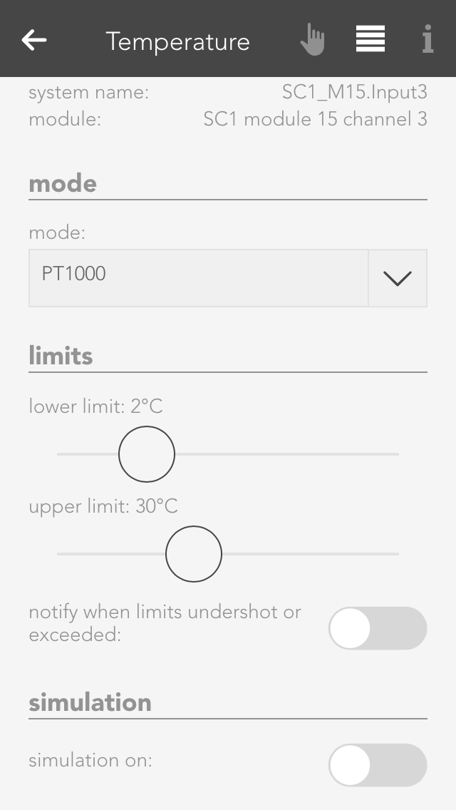
With module A1240, you can only set the temperature limits (as described in the item “scene” above). This module can only accept temperature sensors of type PT1000.
If you posses a module of type A1380, you can connect temperature sensors of type PT1000, KTY81-110 and KTY81-210. To ensure that the modules know which sensor has been connected, you must navigate to the parameter panel for this temperature sensor and select the type under “mode”.
Simulation
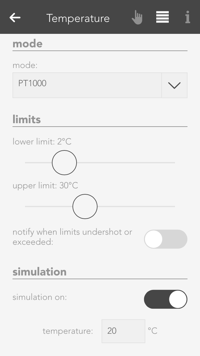
If you want to know what happens if the temperature rises above or falls below a certain value, then you don’t need to cool or heat the temperature sensor. You can use the option “simulation” in the operator panel. Simply activate the checkbox “simulation on” and enter the desired temperature in the input field that appears. Warning, do not forget to deactivate the simulation when you have finished testing.
Usage
Hier werden Dir einige Beispiele beschrieben wie Du einen Temperatursensor verwenden kannst.

Outside temperature
If you want a temperature sensor in your system to determine the outside temperature, you need to add it using the button “add” in the global settings under the item “outside temperature” and drag it to the first position. (More information in this in the documentation for global settings).
External current value for room climate zone
If you want to use this temperature sensor as an actual value for a room climate zone, then you must set the mode to “external actual value” in the desired room climate zone under “settings” and then connect the temperature sensor with it (more detail in the chapter “room climate”).
Scene
In order to link a temperature sensor with a scene, you must first allocate a name to it. Then you can set an upper and a lower temperature limit in the parameter panel that you can use in the scene for the “if …” statement. You can create a scene for the temperature falling below the lower limit or rising above the upper limit.
Logic
If you are an expert with the app “logic”, you can also use this temperature sensor here by connecting the input of a logic element with the current temperature reading.
Szenen
Die Temperatur App bietet folgende Auslöser für evonHOME Szenen (Wenn...):
- Obere Grenze überschritten: Das konfigurierte obere Temperaturlimit wurde überschritten
- Untere Grenze unterschritten: Das konfigurierte untere Temperaturlimit wurde unterschritten
Settings
The general settings for your evonHOME can be found under “all apps” – “settings”.
External access
This is where you determine whether you have Internet access to your evonHOME. If external access is active, then you can access your evonHOME using your evonHOME ID from anywhere.
Global Settings
Global settings let you define what is responsible in your evonHOME for activating wind, rain, frost, dusk states. For example, if you have connected a rain sensor, this is where you would find the settings for your system to display whether it is raining or not. The global settings can be found under “all apps” – “settings”.
Rain

You can connect the rain sensor to the appropriate input of the iX800 controller. IF you also have a weather station or Internet weather, then you need to select which element invokes “rain” in the system. Simply drag the box with the text “iX800” in the item rain to the first place (if more than one box is available) to be able to use the controller’s rain sensor input.
If you have connected your rain sensor to a digital input, then you can select it using the button “add” and drag it to the first position.
Twilight

The dusk sensor can be connected to the dusk input on the iX800 controller. If you also have a weather station or Internet weather, then you need to select which element invokes “dawn/dusk” in the system. Simply drag the box with the text “iX800” in the item dusk to the first position (if more than one box is available) to use the dusk input on the controller.
If you have connected your dusk sensor to a digital input, then you can select it via the button “add” and drag it to the first position.
Wind Alarm

Connect your wind contact to the wind input on the iX800 controller. If you also have a weather station or Internet weather, then select which element invokes “wind alarm” in your system. Drag the box with the text “iX800” in the item wind to the first position (if more than one box is available) to use the wind contact on the controller.
If you have connected your wind contact to a digital input, then select it using the button “add” and drag it to the first position.
Outdoor Temperature

You can select the value you wish to use for the outside temperature by dragging the element to the first position in the item outside temperature.
If you wish to measure the outside temperature using a sensor, you can do this by clicking the button “add”.
In addition, you can define a value for the frost and heat warning (in the parameter panel). As soon as the outside temperature rises above or below this value, a scene or a notification will be invoked.
Geo Coordinates

The sunrise and sunset times can be calculated using the geo-coordinates. These times are then used for the dawn/dusk calculations. To make sure that the dawn/dusk calculation is performed using the geo-coordinates, drag it to the first position in the item dawn/dusk.
The geo-coordinates can be entered using the decimal point format. To find out which geo-coordinates your house has, simply go to www.maps.google.at and search for your house. Right-mouse click on your location and select “what is here?” to display your geo-coordinates (the first value is north and the second east).
If you wish to change the calculated times then activate the option “adjust time for dawn/dusk”. This will let you adjust how many minutes earlier or later you wish dawn and dusk to be.
Simulation
If you wish to simulate what happens if it rains, for example, then you can simply simulate the occurrence of rain by activating the option “simulate rain” in the item “rain” and then activate the option “rain on”. This is also true for wind, outside temperature and daylight. Warning, do not forget to end the simulation when you no longer need it (e.g. deactivate “rain simulation”).
Notification

You can define which events for you would like to receive notification of in the parameter panel.
Updates
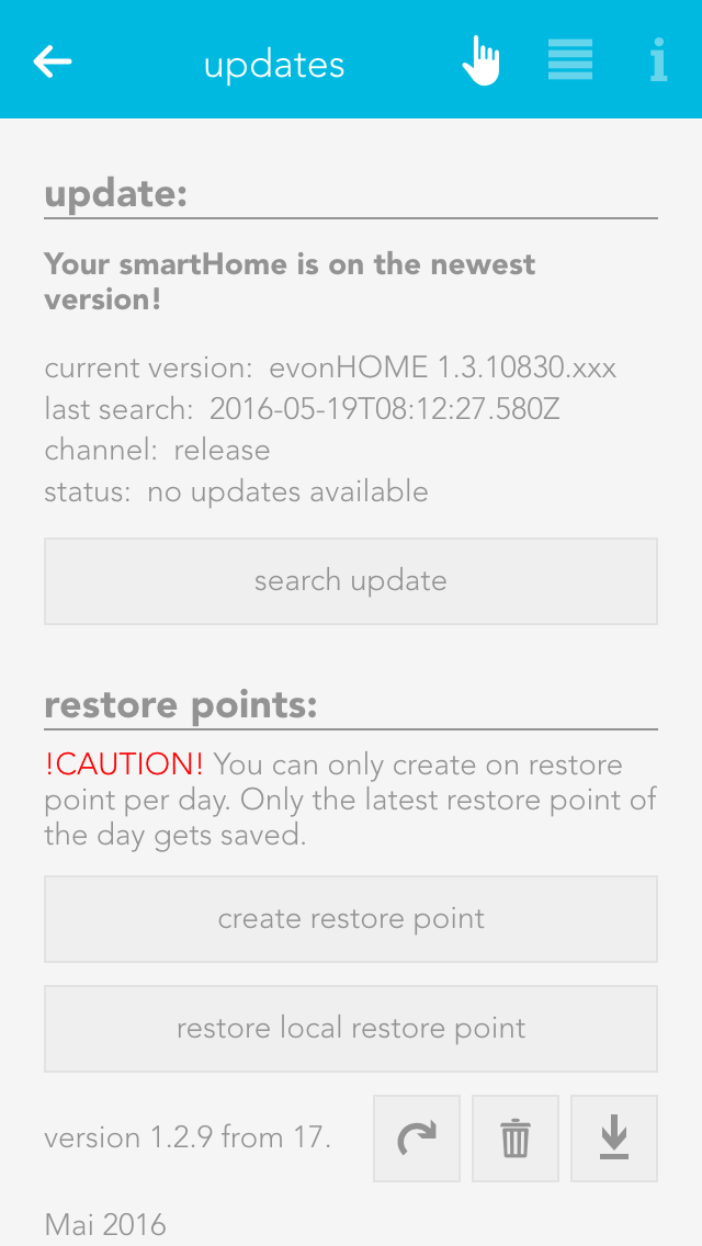
The updates screen lets you make sure your evonHOME is up-to-date. Simply click the button “search for updates” and if an update is available, click “execute update”. If you wish your system to automatically search for updates, activate the setting “search for updates automatically” in the operator panel. You can also see the current version and the time of the last update and the update channel here.
Furthermore, you can create recovery points, which allow you to reset your evonHOME to an earlier state if you have inadvertently maladjusted parameters. Such recovery points are recommended once you have named all your lights, blinds, etc. and have set them up as you require. Use the button “reset to factory setting” to reset your evonHOME to the original factory settings.
Saved recovery points will be shown in a list, where you can delete, recover, or download them at any time.
You can create one recovery point per day. If you create more, only the last one will be saved. In addition, you can also restore your system with a downloaded recovery file by using the button 'restore local restore point'.
A recovery point of your current configuration is created automatically before every update.
System Settings

Project name
You can give your evonHOME any name you like in the system settings.
Controller new start
This function restarts your system. Note that while the system is restarting, you do not have a connection to the CPU.
Manifest
This item shows you whether your visualization is up-to-date. The setting “automatic reload” lets you update your visualization automatically if it is not up-to-date.
System Diagnostic
All information pertaining to your system can be found under the item system diagnostics, such as current version, memory used, IP address, etc.

You can also look at cycle times. This is an indication of the load on your evonHOME system. You can also see the last five peak values. The cycle time is the time required for a complete run of the program.
Time
“Time” lets you see the current time and date used in your controller (server time), the time zone your controller is in and the time of the device you have used to connect to your evonHOME (mobile phone, tablet …).

The time zone lets you allocate the desired time zone to your controller. The item “set time” allows you to set the time in the controller. The button “use client time” allocates the time used by your device (mobile phone, tablet) to the controller. The button “set time manually” lets you set the time and the date for your controller yourself.
Network

This area contains all network settings for the network used by your evonHOME. You can also configure whether the IP address and DNS server should be automatically allocated, or whether you wish to define them yourself.
This app lets you send email notifications via an existing email account. The “test mail” function is used to test the configured settings. You will need to obtain the required settings for the SMTP server from your email provider.
You can either send a test email or you can select “send email” in the “system” tab in a scene “if …” statement. Then all you need to do is enter the sender, recipient, subject and text.
If you wish to register with your Gmail account, then you must allow “less secure apps” in your Gmail account. Simply open the link to the Google Config and click “activate”.
Dictionary
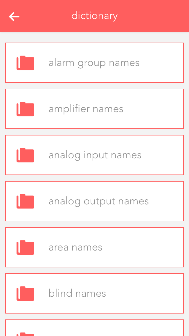
You can edit the pre-defined names in the dictionary. These names will be suggested to you when you wish to name a light, a blind, etc. However, you can even select a different name when naming your elements. The names in the dictionary are only a guide.
Devices
The “devices” app shows you all mobile devices that have been registered in your system.
The “devices” app is under “all apps” – “settings” – “devices”.
Information

If you open a device, the display shows you the name and model of the device in the operator panel. The parameter panel shows detailed information concerning the device.
Configuration

If you wish to receive notifications on this device (e.g. window is open), then you need to activate the checkbox “receive push notifications”.
Hardware
The hardware app lists all modules that are connected to your system. If you wish to obtain a list of module channels, then all elements in this module are clearly displayed and in the correct order, the way they are connected to the module. This view can make it much simpler for you to name the individual elements, since you immediately know which module and which channel you wish to name.
The hardware app is located under “all apps” – “hardware”.
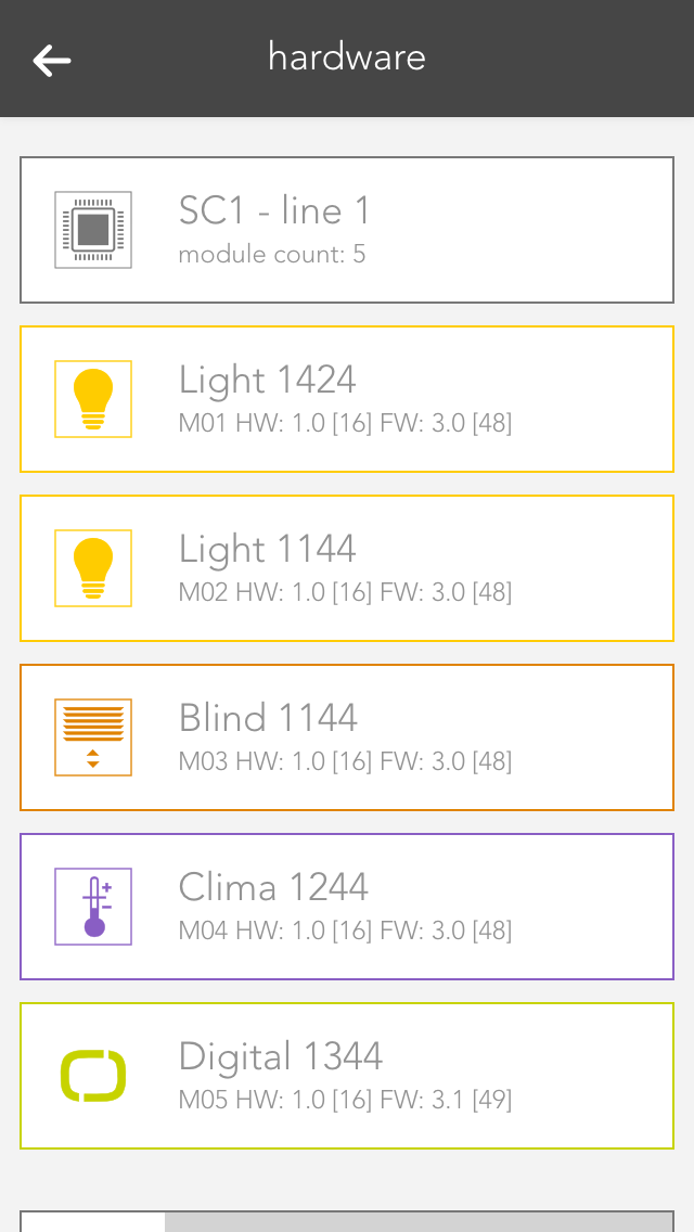
Hierarchically above the modules, you can see which line the module is located in (e.g. SC1 – line 1).
Line

If you open the line, the first thing you will see at the top is general information about the line. The item “cycle time” lets you define the cycle time for your bus line (standard is 200 ms). “Required cycle time” shows the time that is required for the operations. “Total cycle time” is the time required by the bus for a cycle. “Peak” is the peak value of the cycle time. This can be reset using the button “reset peak”.
Modules

By opening a module (click on the right-hand area), you will see all necessary information pertaining to this module. The button “display channels” displays the available channels in this module. The button “reset” resets a module, meaning that this module is reset to factors settings.
Module Channels

Click on the left-hand are of the object panel or on the button “displays channels) in the operator panel to see a list of module channels. Taking a light module as an example, you will be able to see the four channels with their corresponding button/movement detector and a light. This is the exact order that the button/movement detector and light are connected to the module, i.e. channel 1 is the light that is connected on the far left of the module.
Scenes
Scenes are an easy-to-use and yet powerful tool to personalize your evonHOME and adapt the controller to your requirements. Without programming – directly from the app!
Scenes can help you to customize your evonHOME without a single line of code. This is done using the IF THEN principle, i.e. IF a button is pressed, THEN open all the blinds in the room. This principle allows you to combine almost all functions in your controller with each other and to form relationships between them. Creating scenes is not complicated. And if scenes are not sufficient, you can extend your evonHOME with logic.
You can find scenes under “all apps” – “scenes”.
Creating Scenes
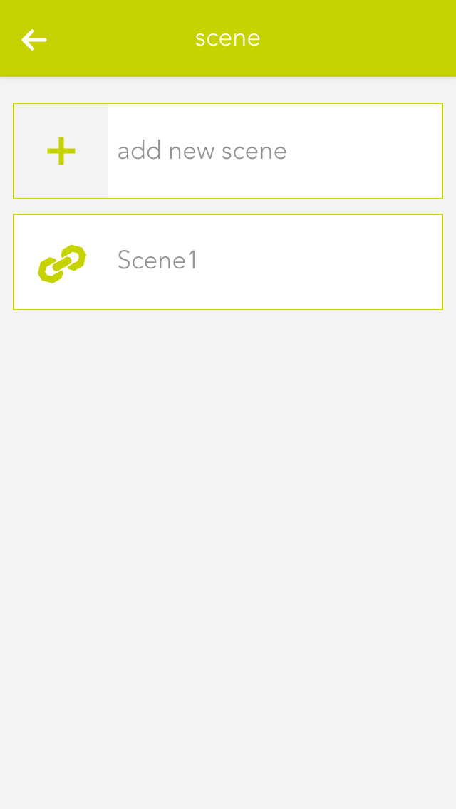
To create a scene, simply open the app “scenes” and select “create new scene”. Then open the operator panel for this scene. Enter the name and optionally a room. Then you can start with the configuration (described below).

If you want to invoke a scene from the visualization, you can do this via the left-hand area of the object panel or via the operator panel with the button “invoke”. Otherwise the scene is invoked automatically if the condition you selected using the “IF” statement is true.
If

To add a trigger condition, click in the area “IF” on the button “add” and a window will open where you can add a trigger condition.
For example, if you add a button then you have three options:
- Pressed
- More press
- Double press
If you want to invoke a scene only via the app, you do not need a trigger condition.
If you wish to add several “IFs”, the scene can be invoked by each individual trigger condition, independently of each other.
Then
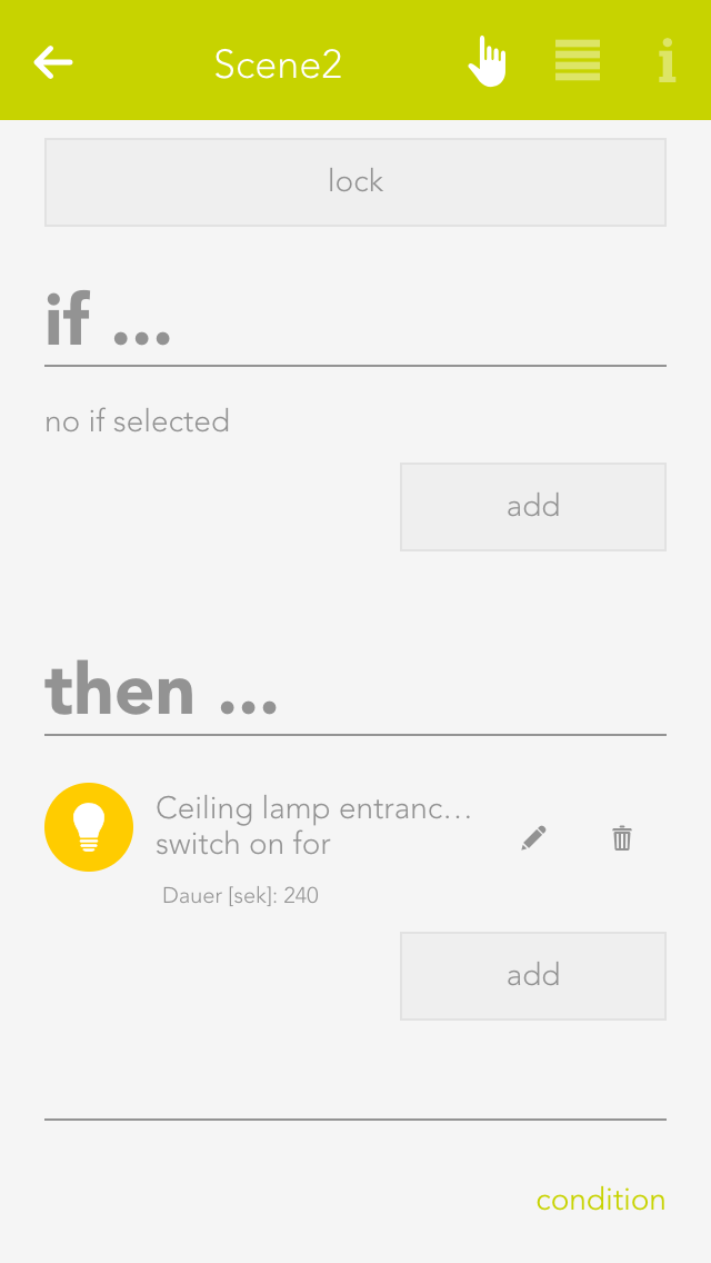
Click on the button “add” in the area “THEN” to select the action you wish to be invoked from the window that opens. For example, you have the possibility to switch lights on or off, to close shading elements or to move them to a specific position, etc.
For example, if you wish to move the blinds to a specific position, then you are offered the opportunity to define the exact position of this blind and the angle of the slats.
Conditions
If you only want a scene to be invoked under certain conditions (for example only if it is raining), then you can do this using conditions.
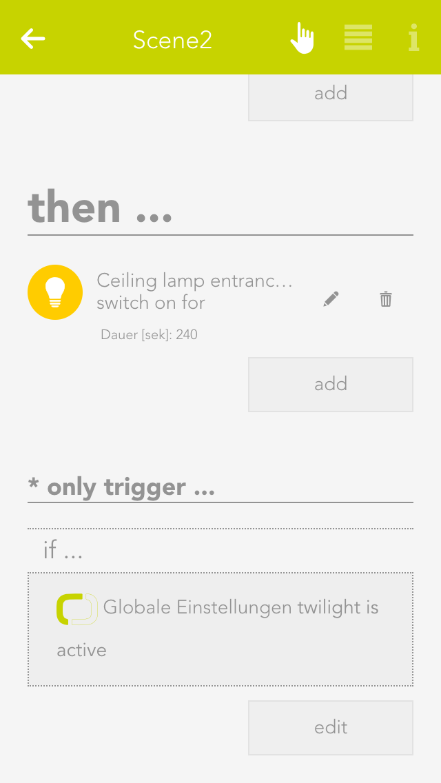
To do this, click at the bottom of the overview on “conditions”. Select here the “only invoke if” and then you can select the corresponding value (e.g. under system – house status the value “rain active”.
After adding this value, you can select others. These are combined using AND or OR logic. If several values are combined via an AND, then all must be active (e.g. “rain active” AND “wind active”) for the scene to be invoked. IF several values are combined via an OR, then at least one of these values must be active (e.g. “rain active” OR “wind active” OR “both active”).
You can edit a condition by clicking on the pencil symbol and delete it by clicking on the trash can symbol.
If a scene is locked due to condition, you can see a padlock in the left-hand area of the object panel, which is also displayed in the operator panel.
Examples
Garden Watering
The following example shows you how to irrigate your garden using a weekly programme and scenes.
You own a garden irrigation system and would like to activate it at defined times. The garden irrigation system is connected to a digital output, i.e. if this output is active, the irrigation system is switched on. If the output is inactive, the irrigation system is switched off.

The first thing you need is a weekly programme. Create the weekly programme in the app “clock” and select “add clock”, then “weekly programme”. Next, name your weekly programme in the operator panel (e.g. garden irrigation).

Now select the day the irrigation system should be active via the “+” button. In the window that opens, define the two times “from “ and “to”. This means the irrigation system should be active between these times (e.g. Monday from 8 am to 10 am). When you have done this, you can see the time until the next switch point at the top of the operator panel.

Once you have entered all the times when you want the irrigation system to be active, you can change to the parameter panel. If you wish the irrigation system to be active outside of the defined times, you can select under “additional trigger” the trigger that you want to also activate the irrigation system (e.g. a switch is pressed). In the item “runtime for additional trigger”, you need to define how long the irrigation system should be active if you activate it via a switch.

Now all you need to do is link the digital output with the weekly programme. You do this via a scene.

Create a scene, select “add” in the IF section and select your weekly programme, then click on “activate”. Select the digital output under “THEN” and select “ON”. Then create another scene and select the weekly programme for “IF” and select “OFF”
Now your garden irrigation system is ready. Make further adjustments to the weekly programme as required.
Szenen
Erstellte Szenen kannst Du auch in andere Szenen im "Dann" Bereich verwenden und diese so z.B. auslösen oder deaktivieren.
Es stehen folgende Funktionen für evonHOME Szenen (Dann...) zu Verfügung:
- Aktivieren: Die Szene wird aktiviert (wenn die Szene vorher deaktiviert war)
- Auslösen: Die Szene wird ausgelöst
- Deaktivieren: Die Szene wird deaktiviert und kann damit von keinem Auslöser (Wenn) gestartet werden
Extended Features
If the steps so far are not sufficient, you can adapt your evonHOME with further functions.
House Status
The “house status” displays the current status of your house and lets you change it.
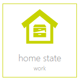
The “house status” is located under “all apps” – “house status”.
Create
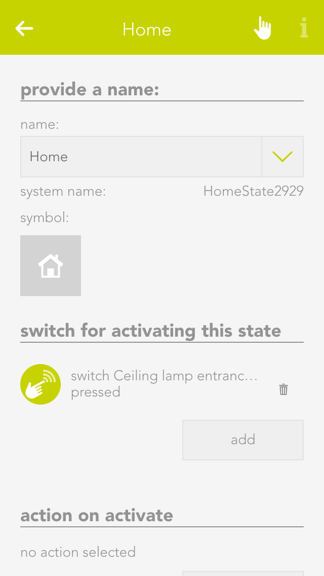
You can easily add a new status for your evonHOME. To add a new house status, click on the element “create status”. The operator panel opens and lets you first allocate a name to your house status. Once named, you can then continue with the configuration (described below).
Each status can be given a name and an icon that is displayed in your evonHOME.
Configuration
For each of your created house stati, you can define which button activates it and should happen if the status changes.
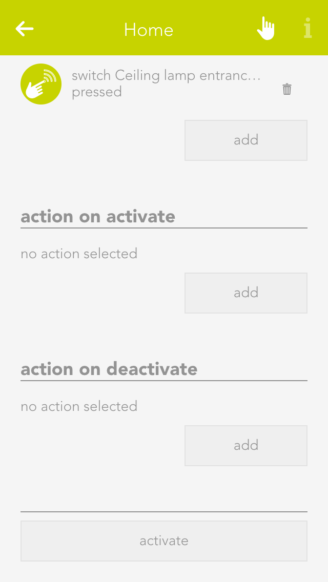
Button to activate this status
Select the button here that allows you to activate the corresponding status
Action when activated
Select here the action that is to be invoked when the corresponding house status is activated.
Action when de-activated
Select here the action that is to be invoked when the corresponding house status is de-activated
Usage
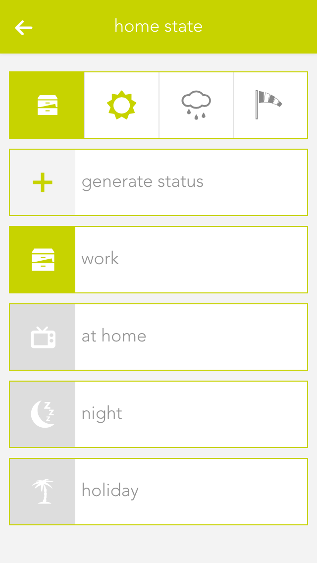
If you want to activate a status via the visualization, you can do this either in the left-hand area of the corresponding object panel or via the operator panel using the button “execute”.
The status that is currently active is displayed both in the object panel and in the house status panel. If you drag the house status to your favourites, then the current active status is displayed there too.
The house status panel not only displays the current status of your house, but also if dawn/dusk, rain or wind are active. You can configure where this information comes from in the “global settings”.
Szenen
Der Hausstatus bietet folgende Auslöser für evonHOME Szenen (Wenn...):
- Aktiviert: Der ausgewählte Hausstatus wurde aktiviert
- Deaktiviert: Der ausgewählte Hausstatus wurde deaktiviert
Der Hausstatus bietet folgende Funktionen für evonHOME Szenen (Dann...):
- Aktivieren: Der gewählte Hausstatus wird aktiviert
Clock
The clock lets you create an alarm clock, a timer or a weekly programme. The next chapters explain how to use them.
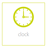
The clock is located under “all apps” – “clock”.
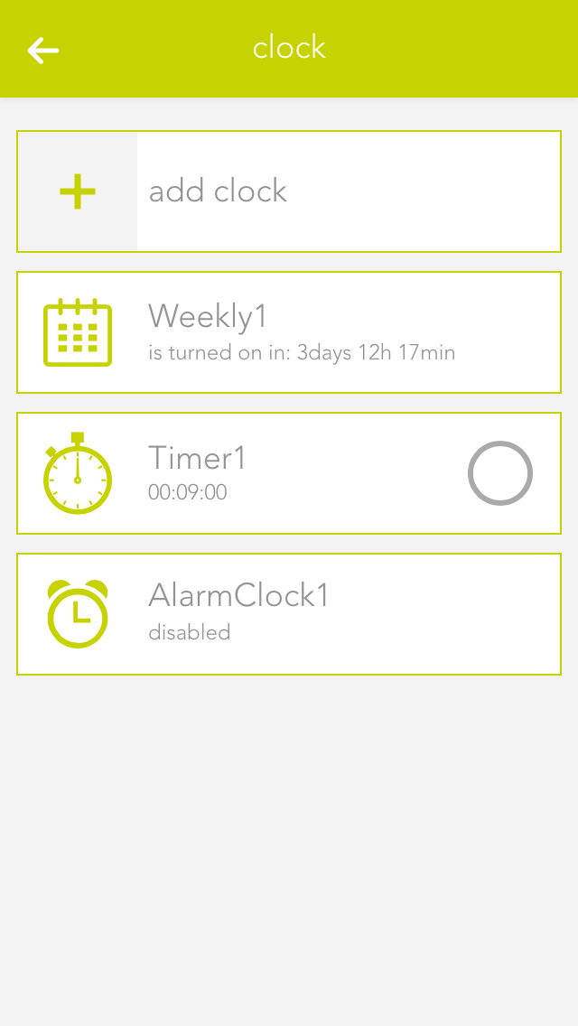
To create an alarm clock, a timer or a weekly programme, simply open the app “clock” and select “add clock”. A window then opens offering you a selection of elements you can create.
Alarm Clock
The app “alarm clock” lets you create an alarm clock that goes off at the time you define and is shut off after a certain time. An alarm clock is intended to be used with a scene to react to the alarm and the end of the alarm.
Using With A Scene
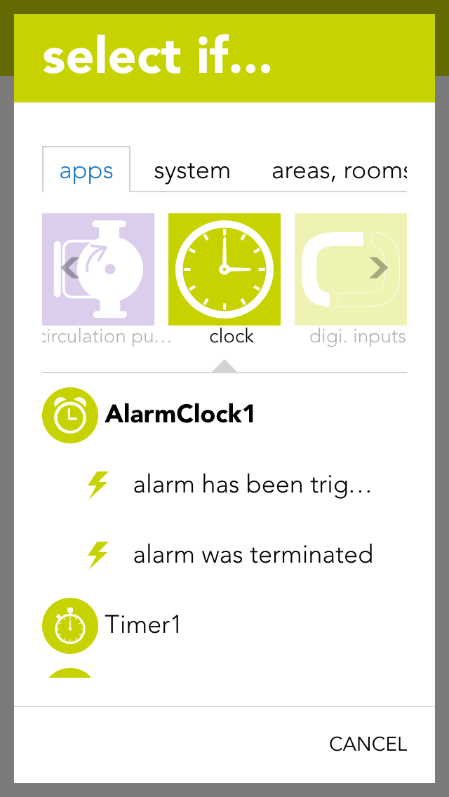
In order to use this alarm with a scene, it must first be named and then you can click on “add” in the scene’s “IF” and select the app “Clock”, unfold the alarm clock and select either “alarm triggered” or “alarm ended”.
Configuration
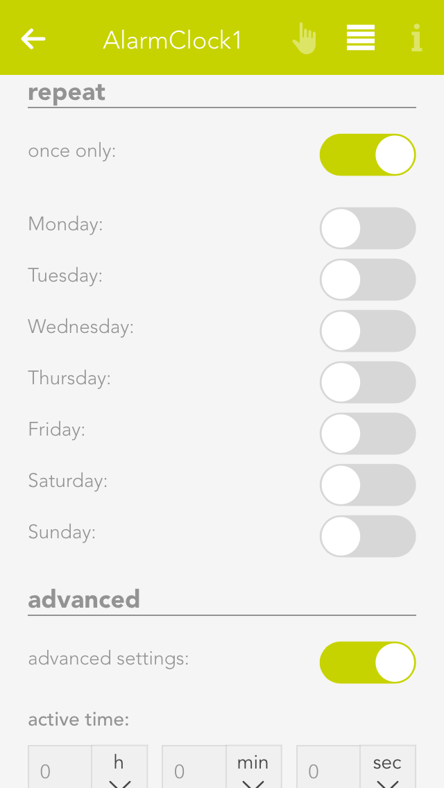
To define the alarm time, simply click on the currently defined time and select the time you wish for the alarm. You must also activate this alarm via the option “activate”.
The item “repeat” lets you select which on weekdays should the alarm be repeated. If you only want the alarm to go off once, select the option “just once”.
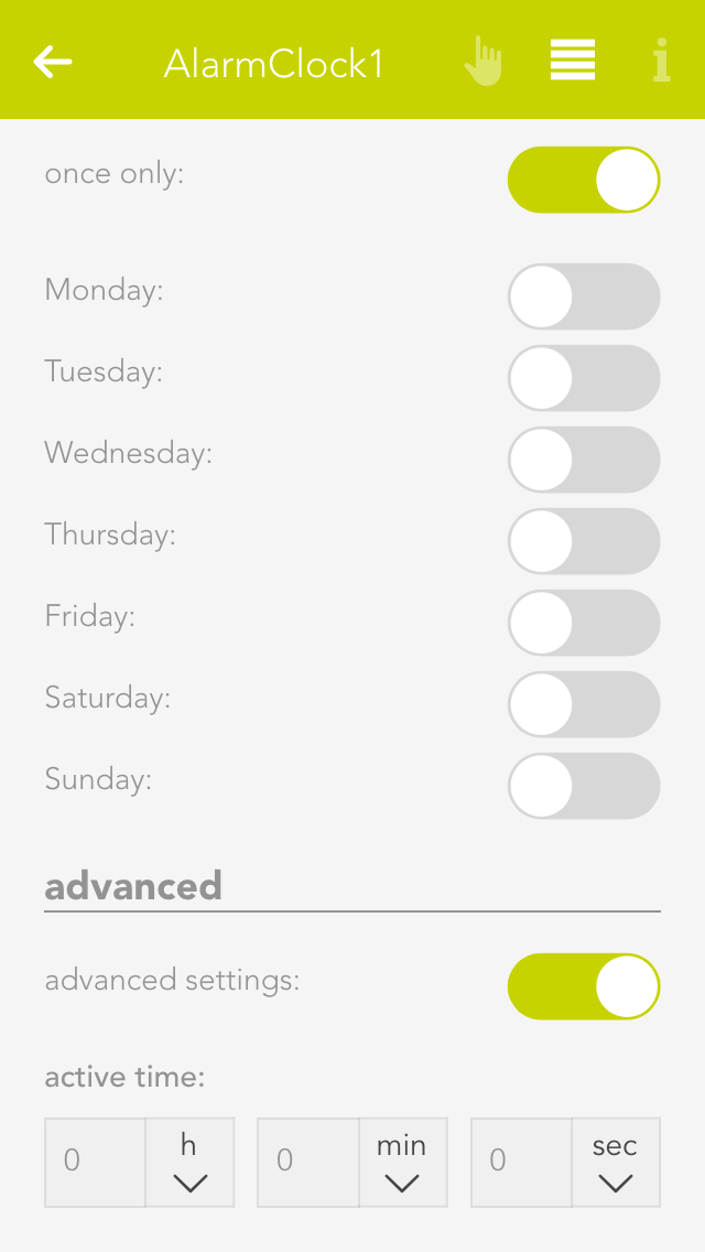
The length of time the alarm is active can be set under “extended” by activating the option “activate extended settings”. You will need the active alarm time if you want the alarm to last for a specific time. For example, if you have activated the alarm for 8pm with an active time of 10 minutes, then the alarm is active from 8 pm till 8:10 pm and then switches itself off. If you haven’t activated this option then the alarm stops directly after the trigger.
Timer
The app “timer” lets you define a countdown that, once the defined time has expired, can invoke a scene. You can also allocate a signal light to this timer that signals when the time has expired.
Operation
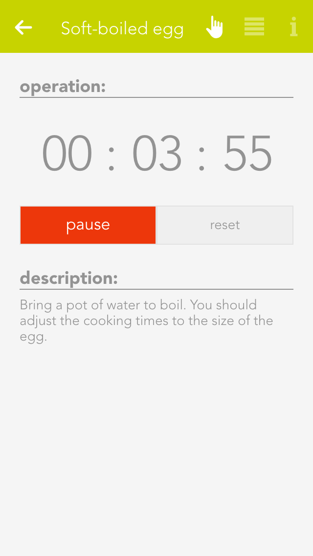
To adjust the time, click on the currently defined timer for this timer in the operator panel under “operation” and change it as you require.
The button “start” is used to start the timer and “reset” to reset the start time. The button “pause” stops the timer and you can continue the timer by pressing “start”.
Using With A Scene
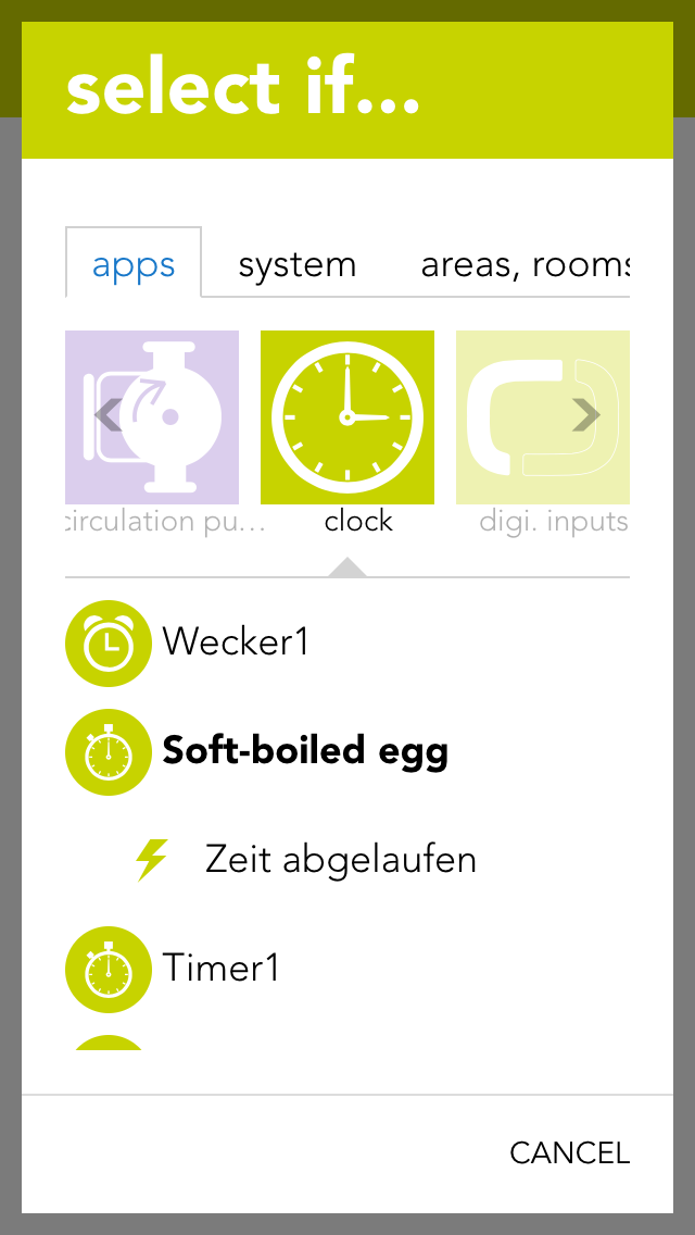
In order to be able to use this timer with a scene, it must have a name. Then you can select the trigger “time expired” in the scene under “IF” and the appropriate action to be carried out when the timer has expired. You can also use the timer in the scene for the “THEN”. This lets you start, stop or reset a timer via a scene.
Configuration
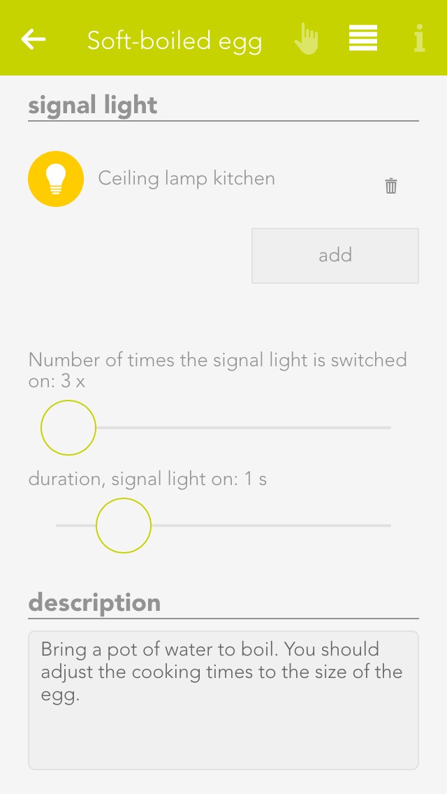
Once you have allocated this timer a name and optionally a room, you can begin with the configuration.
You can add as many lights as you want in the item “signal light” using the button “add”. These lights are intended to flash on and off and the number of flashes can be set via the option “number of flashes”. The duration of each flash can be set via the “duration of signal flash”.
Weekly Program
The app “weekly program” lets you define up to 3 time periods per day in which you can execute actions. In order to be able to carry out an action, a scene must react to the activation and de-activation of the weekly program.
Using With A Scene
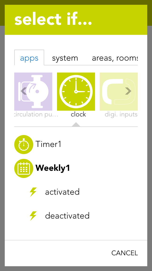
In order to be able to use this weekly program, you must give it a name. Once done, you can select the triggers “activated” and “de-activated” in the scene’s “IF” statement. For example, if a time from 9 am to 10 am has been defined for each Monday, then “activated” is invoked at 9 am and “de-activated” is invoked at 10 am. Furthermore you can use the weekly program in the scene for “THEN” by selecting “switch on once” (“switch on once” is explained in the chapter “configuration”).
Creating And Editing Entries
To create an entry in the weekly program, click on “+” for the desired day. This opens a window where you can configure the entry. You have the following possibilities:
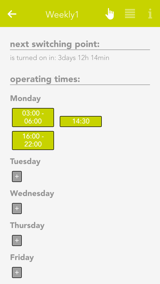
Day
The weekday for which this entry is to be created.
No end time
If you only want to define a start point then activate this option. If a point has no end time, then the weekly program is activated after the time for the “runtime for additional trigger” has expired (located in the parameter panel).
From
This is the start point for your entry
Until
This is the end point for your entry
To edit an entry, click on the previously created entry (in the operator panel) and then proceed the same as for creating the entry.
Configuration
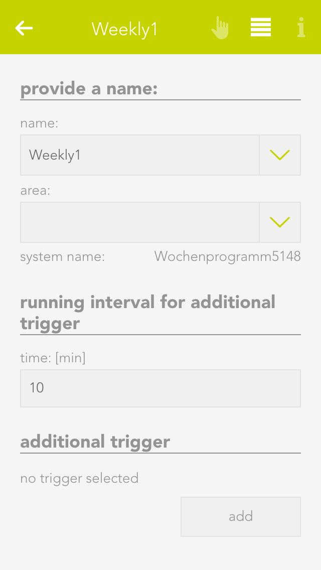
Runtime for additional trigger
If the weekly program is activated once via the additional trigger, then the weekly program remains active for the defined time. If you have an entry without end point, then the weekly program also remains active for this time after the defined time has expired.
Additional trigger
You can add as many additional triggers as you wish that trigger the weekly program once.
Szenen
Die Uhr bietet folgende Auslöser für evonHOME Szenen (Wenn...):
- (Wecker) Alarm wurde ausgelöst: Der konfigurierte Alarm wurde ausgelöst
- (Wecker) Alarm wurde beendet: Der Alarm wurde beendet
- (Timer) Zeit abgelaufen: Die konfigurierte Timer-Zeit ist abgelaufen
- (Wochenprogramm) Aktiviert: Eine der konfigurierten Zeiten des Wochenprogramms wurde aktiv
- (Wochenprogramm) Deaktiviert: Eine der konfigurierten Zeiten des Wochenprogramms wurde inaktiv
Die Uhr bietet folgende Funktionen für evonHOME Szenen (Dann...):
- (Timer) Neu starten: Der Timer wird zurückgesetzt und neu gestartet
- (Timer) Reset: Der Timer wird zurückgesetzt
- (Timer) Start: Der Timer wird gestartet
- (Timer) Stop: Der Timer wird gestoppt
- (Wochenprogramm) Einmalig einschalten: Einmalig einschalten: Das Wochenprogramm wird einmalig aktiviert
Weather Station
The evonHOME weather station is a simple way to receive local weather data and use it in your evonHOME.
The app “weather station” is located under “all apps” – “weather station”.
In order to use this weather station, open the global settings (“all apps” –“settings” – “global settings”) and drag the weather station to the first position for wind, rain, outside temperature and daylight (it is also possible to only use the weather station for wind).
Create
To use the evonHOME weather station, follow the following steps:
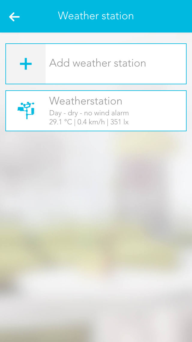
Mounting
Mount the weather station following the documentation (follow the instructions concerning the direction and distances carefully)
Connecting
Connect the evonHOME weather station 2-wire bus cable to the evonHOME CPU iX800 – ensure the polarity is correct (A-B) (recommended cable J-Y(ST)Y 2 x 2 x 0,8).
Power supply
Supply the evonHOME weather station with power (see documentation).
Add
Add a new weather station. If you have done everything correctly, a connection is established and your weather data are updated every second.
Note: Only one weather station can be operated by the CPU iX800.
Configuration

Wind alarm settings
The wind alarm settings let you define a wind speed above which an alarm is triggered. You can also define hysteresis so that the wind alarm does not trigger and end continuously should the wind speed oscillate around the alarm value. If you want that the wind alarm is active only after a certain time, then you need to enter a delay. This means that this time must be longer than the time set for “wind speed alarm”, so that a wind alarm is triggered.
Dawn/dusk settings
These settings let you define the light levels when dusk/dawn is active and inactive. Hysteresis and delay have the same functions as described previously.
Operation

In the Operatorpanel of the Weather Station, you will find several statistics and charts, which provide you with an insight on the measured values.
Szenen
Die Wetterstation bietet folgende Auslöser für evonHOME Szenen (Wenn...):
- Aufgehört zu regnen: Das Ende des Niederschlags wurde erkannt
- Außentemperatur Max-Limit überschritten: Das konfigurierte Max-Limit der Außentemperatur wurde überschritten
- Außentemperatur Min-Limit unterschritten: Das konfigurierte Min-Limit der Außentemperatur wurde unterschritten
- Regen (Niederschlag) erkannt: Der Beginn des Niederschlags wurde erkannt
- Sonnenaufgang: Der Sonnenaufgang wurde erkannt
- Sonneneinstrahlung-Ost Max-Limit überschritten: Das konfigurierte Sonnenstrahlung Max-Limit im Osten wurde überschritten
- Sonneneinstrahlung-Ost Min-Limit unterschritten: Das konfigurierte Sonnenstrahlung Min-Limit im Osten wurde unterschritten
- Sonneneinstrahlung-Süd Max-Limit überschritten: Das konfigurierte Sonnenstrahlung Max-Limit im Süden wurde überschritten
- Sonneneinstrahlung-Süd Min-Limit unterschritten: Das konfigurierte Sonnenstrahlung Min-Limit im Süden wurde unterschritten
- Sonneneinstrahlung-West Max-Limit überschritten: Das konfigurierte Sonnenstrahlung Max-Limit im Westen wurde überschritten
- Sonneneinstrahlung-West Min-Limit unterschritten: Das konfigurierte Sonnenstrahlung Min-Limit im Westen wurde unterschritten
- Sonnenuntergang: Der Sonnenuntergang wurde erkannt
- Sturm erkannt: Das konfigurierte Wind-Limit wurde überschritten
- Sturm vorbei: Das konfigurierte Wind-Limit wurde unterschritten
Shading Control
shading control let automatically control your blinds based on the sun. Now you have always enough brightness, without dazzling yourself. You can decide on yourself, how much light you want.
In summer, your blinds can close automatically at high outside temperatures while you can use the energy of the sun in winter. Of course you have the possibility to control your blinds via app or switch as usual.

You can find shading control under „settings“ - „shadingcontrol“.
Create
To use the shading control, you have to add facades. A facade is an own control unit with controls its assigned blinds by cardinal directions.

You can add as many facades as you want under „settings“ - „shading control“. Preferably you add as many facades as outside walls you have. Usually there are 4 facades, which are configured with north, east, south, west or if the building is arranged diagonally the sun with northeast, southeast, southwest, northwest.

In the parameter panel of the facade, the direction can be set. Choose the best fitting of the 8 available directions. Assign your facade a name to order it easier later.
In addition to the direction you can choose a type. You can always add only blinds of the same type.
Configuration
To control your blinds automatically you have to assign them to a facade. you can do that in the parameter panel of an existing facade under „elements“.
ATTENTION! Blinds should not be assigned to several facades. Take care of blind groups too.

If you also want to use the shading control to use heat of the sun, you can add the inside temperature under „thermostats“. You can also leave this area empty, if you do not want to enable heat using.

On the bottom of the parameter panel you can see a table with control positions. This table is the base of the shading control. You can set blind positions to a specific sun height and also the angle at jalousies.
With the „submit“ button you can accept the set values to the facade. You can also set the values to all facades or reset it to default values.

On the bottom of the parameter panel you can set additional parameter. The minimal brightness must be above to control the blinds by the table. Among this value the blinds keeps open.
If the heat protection is active, all blinds will close completely, if the outside temperature is above the setting.
On using a thermostat and heat using is active, all blinds will open completely, if the outside temperature and inside temperature is among the setting.
Control
The shading control helps you to reduce manual interactions with blinds. After the configuration of the shading control no more manual control is needed anymore. Anyhow you have always the possibility to deactivate or activate the control or to monitor it.

The static panel of the shading control provides summary information of the control. Values like sun height and lighted facades are listed.
Beside this, you can disable or enable the whole control with one click. The function „reactivate automatically“ activates facades at a specific time, if they were deactivate by manual interaction for example. If you want to exclude a facade from this function, you can do this with „lock facade“ in the parameter panel of a facade.

The Object Panel shows the configured direction. The icon is colored orange, if the facade is lighted by the sun. On the right side the current blind state is shown. If the facade is disabled, the whole panel is greyed out.

The operator panel of a facade provides its main information. Sun height, light state and outside brightness from your weather station are some of listet values.
Assigned blinds are listet too.
On the bottom side of the operator panel the control table is listet. The line with the current sun height is marked. If the facade is active, lighted and the min brightness is reached, the marker gets orange and the position of this line will be controlled . If heat using or heat protection is active, they have priority.
Scenes
Shading control provides following functions for evonHOME scenes (then..):
- Activate all: All facades will be activated, except locked ones.
- Activate facade: Facade will be activated, except it is locked.
- Deactivate facade: Facade will be deactiavted.
Internet Weather Station
The Internet weather app lets you call up data for a specified region and use it for your evonHOME.
The app “Internet weather” is located under “all apps” – “Internet weather”.
Create
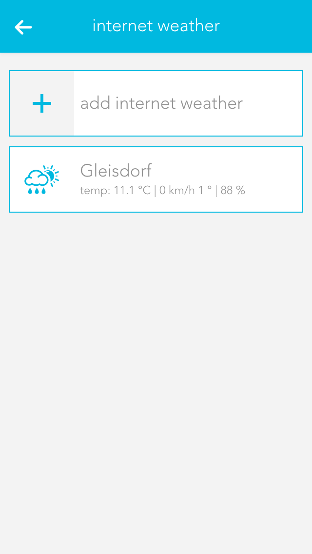
Click on the element “add weather station” to add a new weather station. This opens the operator panel where you need to define a name for your weather station. Enter the API key and your location in the item “weather underground API key”. This is provided by WeatherUnderground (http://www.wunderground.com) once you have registered there. Once you have done this successfully, you will receive weather data for the specified location.
If you want the use this weather station for your evonHOME, then drag this weather station to the first position for wind, rain, outside temperature and daylight in the app “global priorities”. (For example, if you only want to use the outside temperature of this station, then only drag the weather station to the first position for the outside temperature).
Bedienung

Die Anzeige im oberen Bereich liefert aktuelle Messwerte der nächstgelegenen Wetterstation.
Die Vorhersage liefert Wetterprognose-Daten vom aktuellen Tag und der kommenden 3 Tage. Diese Daten können in der Logik oder als Bedingungen in Szenen verwendet werden.
Configuration
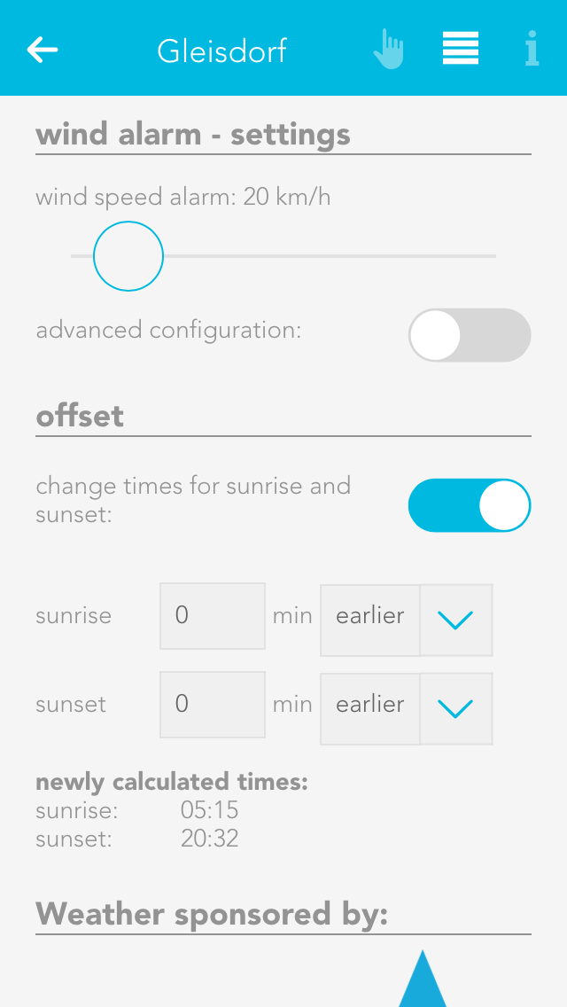
Wind alarm settings
This is where you define the wind speed that you wish to trigger an alarm. If you also wish to define hysteresis and a delay, then activate the option “extended settings” and select hysteresis and delay. If the wind speed exceeds the value defined for wind alarm, then the alarm is triggered. Now the wind speed must fall below the defined hysteresis value (below the wind speed alarm value) for the alarm to be reset. The delay defines how the wind speed must be above the defined limit for the alarm to be triggered.
Offset
If you are not satisfied with the time for sunset and sunrise, you can change then by activating the option “change sunrise and sunset times” and changing the times accordingly.
Door
The app “door” lets you create a door for your evonHOME. You can link a camera, a bellring button, a bellring and a door opener contact to such a door.

The app “door” is located under “all apps” – “door”.
Configuration
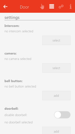
Intercom
Choose a connected intercom. "Camera" and "Bellpush" will automatically be assigned.
Camera
This field lets you select a camera for this door. The camera image is then always displayed on the operator panel.
Bellpush
Use the button “add” to add one or more buttons you wish to use to ring the doorbell.
Doorbell
Select the digital output that is connected with the doorbell.
Door opener
Select the digital output connected to the door opener using the button “add”.
Signal light
If you in a room where it is not possible to hear the doorbell, you can select a light in this room that will flash when someone rings the doorbell
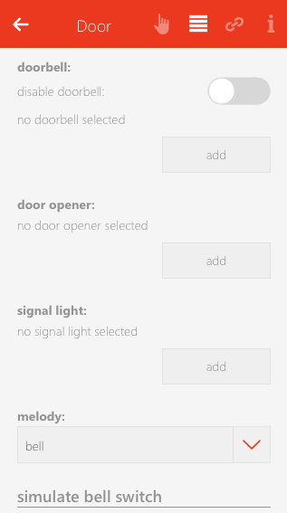
Number of flashes
Define the number of times the signal light is to flash when someone rings the doorbell.
Signal light on time
Defines how long the signal flash is to be.
Door open time
Defines how long the door remains open, if you open it via the app.
Doorbell time
Defines how long the digital output for the doorbell is to remain active.
Melody
If you want a melody to play on your smartphone, or tablet etc. when someone rings the doorbell, then you can choose here between two melodies.
Simulate
You can simulate the doorbell button press using the button “ring” to test whether you have satisfactorily configured all options according to your requirements. This has the same effect as if someone had really pressed the doorbell.
If you want to be able to use the built in microphone and speaker of your intercom to talk to visitors, we recommended to download and use the following apps:
iOS - https://itunes.apple.com/at/app/mobotix/id527836206?mt=8
Android - https://play.google.com/store/apps/details?id=org.abionix.axviewer&hl=de
Operation
If you open the operator panel for your door, then you can see the camera image (if a camera is linked to this door) and a button “open door” that lets you open this door (if a door open contact has been selected).
As soon as someone rings the bell for this door, you will receive a notification and a photo is taken of the moment the bell was rung that you can see when you open the notification.
Szenen
Die Tür bietet folgende Auslöser für evonHOME Szenen (Wenn...):
- Klingel läutet: Die Klingeltaste wurde betätigt
- Tür wird geöffnet: Der elektrische Kontakte zum Türöffnen (z.B.: Motorschloss) wurde betätigt
Die Tür bietet folgende Funktionen für evonHOME Szenen (Dann...):
- Aktuelles Kamerabild speichern: Das aktuelle Kamerabild der zugewiesenen Kamera wird gespeichert
- Öffnen: Der elektrische Kontakte zum Türöffnen (z.B.: Motorschloss) wird aktiviert
- Türklingel aktivieren: Die Türklingel wird aktiviert (wenn diese vorher deaktiviert war)
- Türklingel auslösen: Die konfigurierte Türklingel wird ausgelöst
- Türklingel deaktivieren: ** Die Türklingel wird deaktiviert
Window
The app “windows” lets you operate and configure all windows in your system. You also have pre-defined central functions such as “open all windows” and “close all windows”.
The windows app is located under “all apps”.
Window Settings
You can configure general settings for all windows in the window settings area located under “all apps” – “settings”.
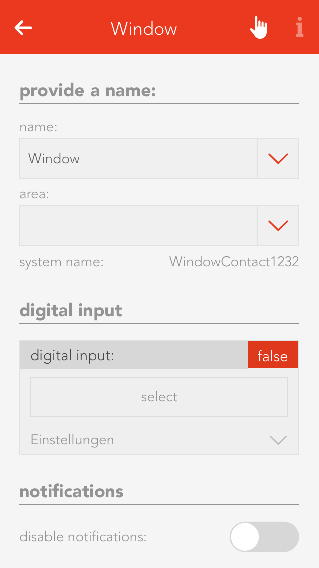
Notifications of open windows and rain/wind
If you wish to receive a notification if a window is open and it is raining or is windy, then you must activate this option.
The item “open windows” shows you a list of all open windows. The button “update” reloads the list of all open windows.
Szenen
Das Fenster bietet folgende Funktionen für evonHOME Szenen (Dann...):
- Auf Position fahren: Das Fenster wird auf eine frei wählbare Position gestellt
- Öffnen: Das Fenster wird vollständig geöffnet
- Schließen: Das Fenster wird vollständig geschlossen
- Stoppen: Die aktuelle Fahrbewegung des Fensters wird gestoppt
Types Of Window
You have the possibility of integrating two types of window into your system, by window contacts or electric windows.
If you have simply just one window contact connected to a digital input, then you must create a “window contact”. However, if you have an electric window that you wish to integrate into your system, then you must create an “electric window”. Electrical windows are connected to blind modules, since they work according to the same principle.
Window Contact
Create
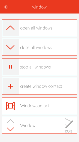
To create a window contact, open the window app under “all apps” and select “create window contact”. This opens the operator panel and the newly created window contact. It is important to first give the contact a name and optionally the location of the window.
Configuration

Select the digital input the window contact is connected to in the item “digital input”.
The object panel for this window contact will display whether this window is open or closed. If “open” and “closed” are reversed, i.e. the object panel shows a window to be open although it is actually closed, then activate the option “invert” in the operator panel.
You can de-activate notifications for wind and rain in the tem “notifications”.
Using With A Scene
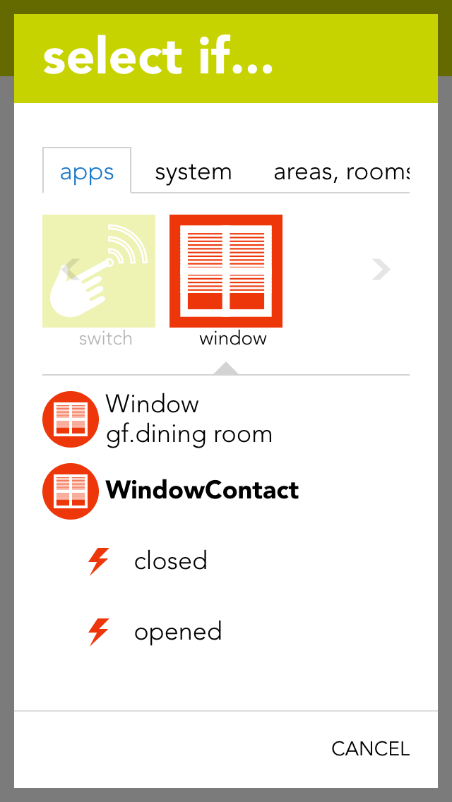
A scene lets you react to the opening and closing of a window by selecting the triggers “has been opened” or “has been closed” in the “IF…” statement and then selecting what should happen in the “THEN ..” statement.
Electric Window
Create
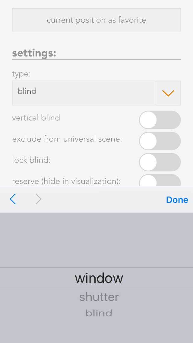
To create an electric window, open the app “shading” and select the blind the window is connected to. Navigate to the parameter panel and select the “type” “window”.
Operation
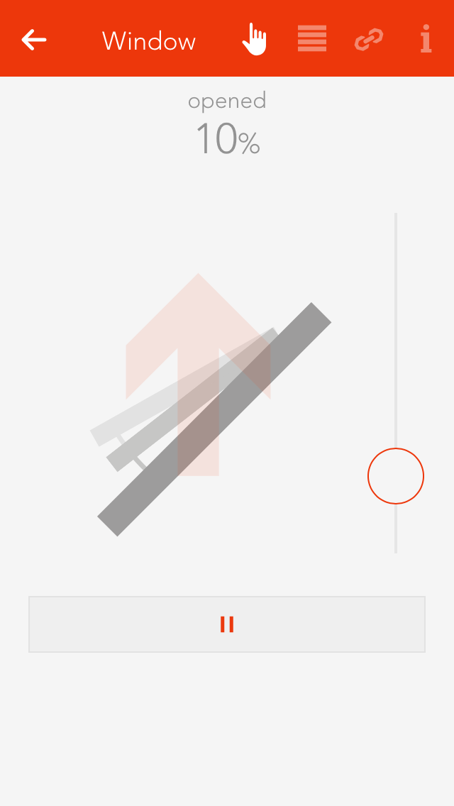
You can operate an electric window either via the object panel using the arrows on the left-hand side or via the operator panel using the buttons and the slider.
Adjust Opening Times
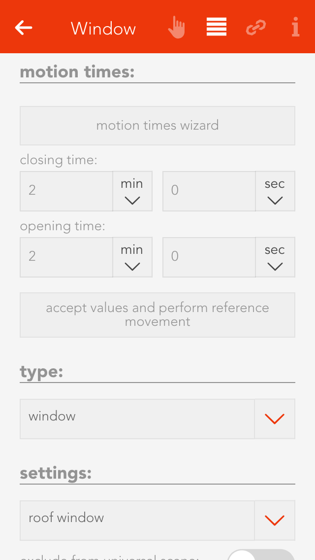
If you know exactly how long your window takes to open and close, then enter the times directly into the fields “closing time” and “opening time”, then click on the button “use values and run reference”.
If you do not know the times, simply use the wizard to determine the opening and closing times. Follow the wizard’s instructions and the times will be automatically entered and a reference activity carried out.
Configuration
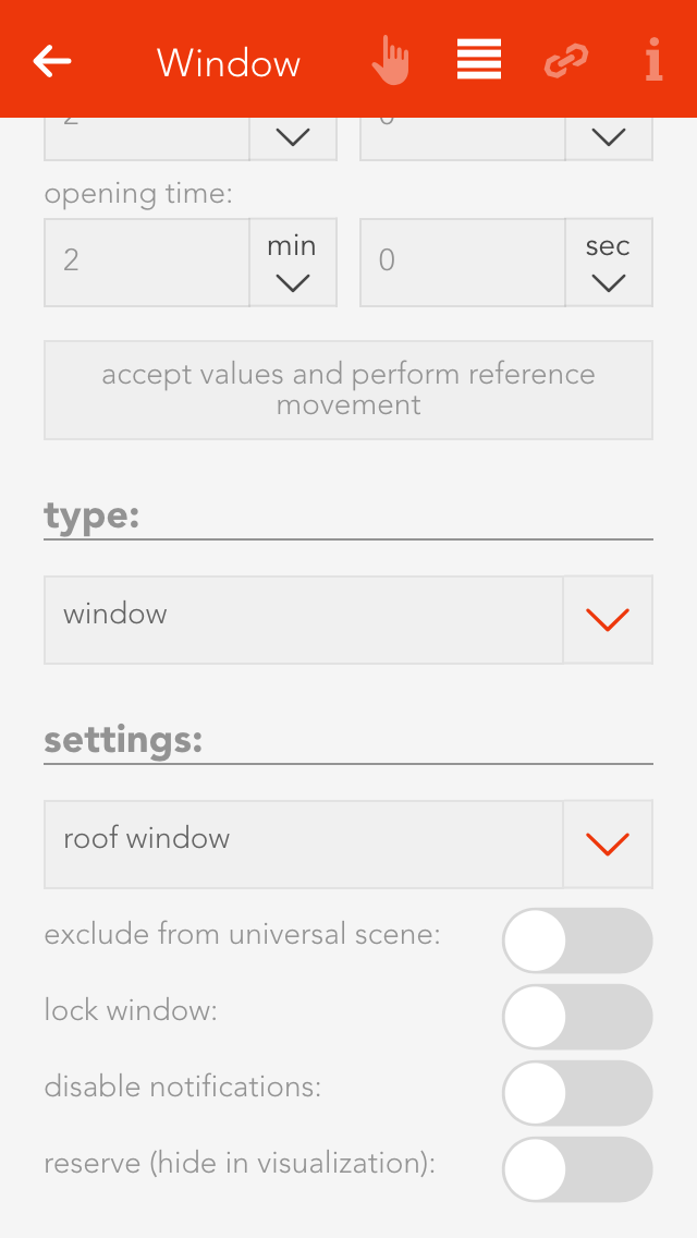
Type
If you want to convert this electric window back into a blind, then you can easily do this by selecting the type “blind”.
Except from universal scene
A universal scene “open all windows”, for example, would open all windows. However, if you wish a window to be excepted from this universal scene, then activate this option.
Lock window
This option lets you lock a window, i.e. the position cannot be changed, neither via the visualization nor via a button.
Deactivate notifications
If you do not wish to receive notifications for this window, then activate this option.
Reserve (hide in visualization)
“Reserve” lets you hide unused channels. You can unhide them via the app “hardware” and the corresponding module.
Couple With
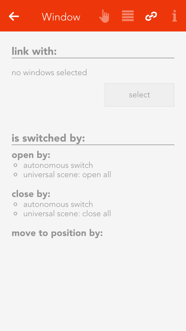
If you want two windows to always have the same position, this can be done by coupling them. Simply select the button “select” in the item “couple with” and choose the window you wish to couple this window with.
Using With A Scene
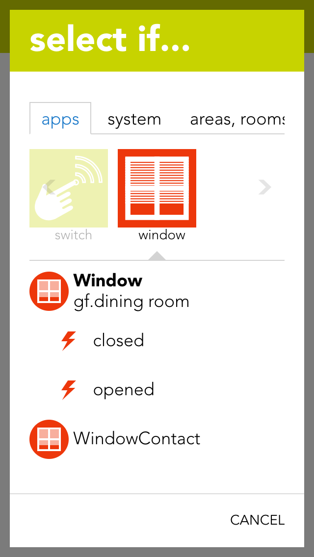
A scene lets you react to the opening and closing of a window in that you select “has been opened” or “has been closed” in the “IF” statement and then select what should happen as a consequence in the “THEN …” statement.
You can also select the actions “go to position” (go to a window position you have defined), “open” and “close” in the “THEN” statement of a scene.
Alarm System
The app “alarm system” lets you create a personal alarm system for your evonHOME. The alarm system is divided into a central alarm system and one or more alarm groups. Alarm groups divide the alarm system into several areas.
The app “alarm system” is located under “all apps” – “alarm system”.
Operate
The initial password for the Alarm System is set to "1234".
It is highly recommended to change it on initial setup. You can find the related options in the SettingsPanel (See section configuration).
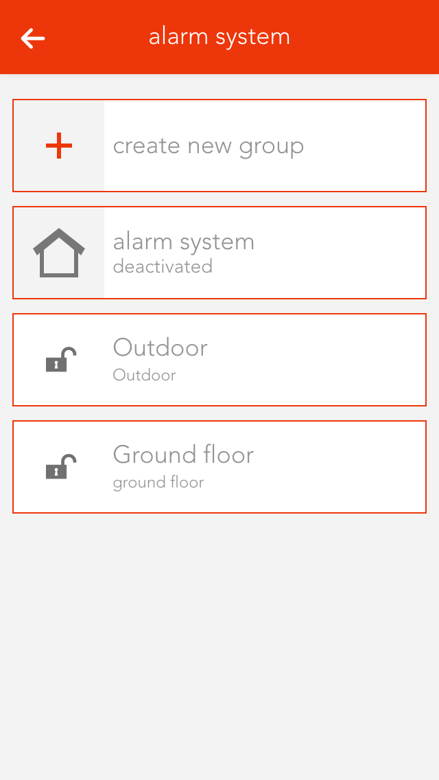
If the alarm system or one or more alarm groups have been activated, the defined activation delay for each alarm group must first expire before the alarm can be triggered. Once the activation delay has expired, if a movement detector is triggered then a trigger delay is activated. During this time, the alarm system can be de-activated without an alarm being triggered. Once the trigger delay has expired, the silent alarm is triggered and a notification is sent. Once the silent alarm time has expired, the actual alarm is triggered and a further notification is sent and the outputs linked to the alarm system are switched.
Activation time is necessary for the following situation: you want to leave the house and activate the alarm before you go. To make sure that you do not inadvertently trigger the alarm yourself, you need the activation delay.

If you want to activate the alarm system, you can either do this via the app by opening the alarm system (“all apps” –“alarm system”) and select the button “activate” in the operator panel for the alarm system, or you define a button to activate the alarm and you use this button (how you do this is described in the chapter configuration). Deactivating the alarm is done the same way via the app, only that you have to enter a password. Deactivation via a button works identically to activation.
You can also find a history of past events in the OperatorPanel of the alarm system which gives you detailed records about the dates and times when it got triggered, activated or deactivated.
Warning, since the alarm system can be deactivated without a password using a button, you need to select a button that is not immediately visible!
Szenen
Die Alarmanlage bietet folgende Auslöser für evonHOME Szenen (Wenn...):
- Alarm wurde ausgelöst: Der Alarm wurde durch einen konfigurierten Auslöser aktiviert
- Alarm wurde gestoppt: Der Alarm wurde gestoppt
- Alarm wurde still ausgelöst: Der stille Alarm wurde ausgelöst
- Alarmanlage ist aktiviert: Die Alarmanlage wurde aktiviert
- Alarmanlage wurde deaktiviert: Die Alarmanlage wurde deaktiviert
Die Alarmanlage bietet folgende Funktionen für evonHOME Szenen (Dann...):
- Aktivieren: Die Alarmanlage wird aktiviert (Achtung: die Alarmgruppe muss zusätzlich aktiviert werden).
- Deaktivieren: Die Alarmanlage wird deaktiviert (Die Alarmgruppe bleibt aktiviert)
- Kontrollgang beenden: Die Funktion "Kontrollgang" wird beendet, die Alarmanlage wird wieder scharf geschaltet.
- Kontrollgang starten: Die Funktion "Kontrollgang" wird für die eingestellte Dauer aktiviert.
- Alarmgruppe aktivieren: Die ausgewählte Gruppe wird scharf geschaltet.
- Alarmgruppe deaktivieren: Die ausgewählte Gruppe wird unscharf geschaltet.
Configuration

Duration of silent alarm
Enter the time for silent alarm here.
Automatically deactivate alarm after
Automatically deactivates the alarm after expiration of this time. This is important if you are holiday and something triggers the alarm. If this option was not available, the alarm would never switch off and your neighbours would not be too pleased with you.
Duration of patrol
This is the time the alarm should be deactivated for while you make a patrol.

Button to activate the alarm system
Select a button to activate the alarm system.
Button to deactivate the alarm system
Use the button “add” to select a button to deactivate the alarm system. Warning! This button can deactivate the alarm system without a password. Consider the use of such a button carefully.
Button to start patrol
Select a button to let you start a patrol.
Button to end patrol
Select a button to tell the system you have completed your patrol.

Status light
Select a light that will flash twice when the alarm system has been activated and once when deactivated.
Actions when alarm triggers
Use the button “add” to select all the actions you wish to happen when an alarm is triggered (e.g. switch lights on, activate siren, etc.).
Actions when alarm stops
Select what should happen when the alarm is deactivated. Caution! Do not forget to deactivate the actions started when the alarm was triggered.
Change password
Change the password to deactivate your alarm system.
Alarm Group

An "Alarm Group" represents a section of your alarm system which you want to secure. You can create an unlimited number of groups and use them to arrange your house into various segments. This makes it possible to create different settings for each group and only activate the ones you need.
You can, for example, create a new alarm group for each floor and by using a scene, only secure the ones which are not occupied at the moment.
Operation

The OperatorPanel shows you the current state of the group. If the lock is closed, the group is currently active and will be taken into account when you activate the alarm system.
To change the state of the group, you can click on the small lock in the ObjectPanel of the group or use the button in the OperatorPanel.
Be aware that once the alarm system is activated, you can not change the state of each alarm group. If you want to activate or deactivate a group, you will have to deactivate the alarm system first.
Configuration

Activation delay
If the alarm system and this group have been activated, then the alarm in this group can only be triggered after this time has expired. (Important if you wish to leave the house without triggering an alarm yourself).
Trigger delay
The silent alarm is triggered after this time has expired.
Trigger if
Select all the triggers that you wish to be able to set off this alarm.

camera
Select one or more cameras which will capture up to 6 images if the alarm goes off. You can change the interval for the captured images by using the provided slider. For example: If you set the interval to 2 seconds, each camera will try to capture an image every 2 seconds until 6 images are recorded. You can view the captured images in the "pictures" section below this setting.
Test alarm
The button “test alarm” lets you trigger an alarm in this group. The group and the central alarm system are activated, the panel is closed and an alarm is triggered. Use this to test your alarm system.
Bathroom Heating
“Bathroom heating” lets you configure suitable heating systems and control their times.
These functions are located under “all apps” – “bathroom heating”.
Operation
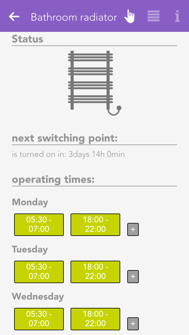
To add a new bathroom heater, click on the element “add”. First allocate a name to your bathroom heater in the parameter panel, then you can continue with the configuration (described below).
Szenen
Der Badheizkörper bietet folgende Auslöser für evonHOME Szenen (Wenn...):
- Wurde Ausgeschaltet: Der Badheizkörper wurde ausgeschaltet
- Wurde Eingeschaltet: Der Badheizkörper wurde eingeschaltet
Der Badheizkörper bietet folgende Funktionen für evonHOME Szenen (Dann...):
- Einmalig einschalten: Der Badheizköper wird für die Zeit des zusätzlichen Auslösers eingeschaltet
Configuration
You can determine what time each of your bathroom heaters should be on. You do this by defining the operating times in the operator panel. You can define one or more time intervals where your heater should heat for each weekday.
Apart from the operating times, you can also define a button to activate each bathroom heater, where it is connected and whether it should be switched into maintenance mode.
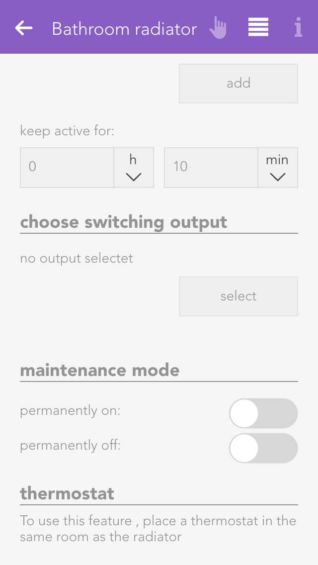
Additional trigger
Select the trigger and the duration for which the bathroom heater should additionally be activated for a short period of time.
Select socket
This lets you define which socket your bathroom heater is connected to.
Maintenance mode
This lets you permanently switch the maintenance mode for the bathroom heater on or off.
Circulation Pump
“Circulation pump” lets you configure and control the times for suitable pump systems.
These functions are located under “all apps” – “circulation pump”.
Configuration
You can define the operation times for each one of your circulation pumps. This is done by defining the operating times in the operator panel. You can define one or more time intervals for each weekday when you wish the circulation pump to be in operation.
In addition to the operating times, you can also define intervals within the operating times, which trigger activates them, where they are connected and whether they should be put into maintenance mode.
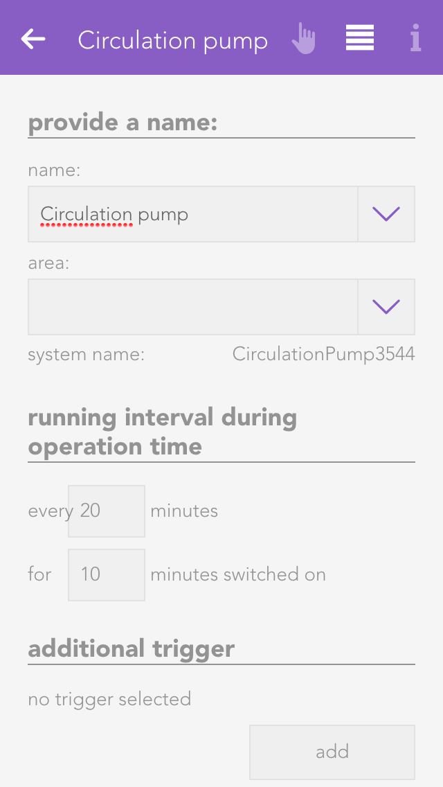
Active interval during operating time
Define the intervals within the operating time you wish to circulation pump to be active.
Additional trigger
Select the trigger and the duration for which the circulation pump should be additional active for a short period of time.
Select socket
Define which socket the circulation pump is connected to.
Maintenance
Switch the circulation pump permanently on or off for maintenance purposes.
Operation
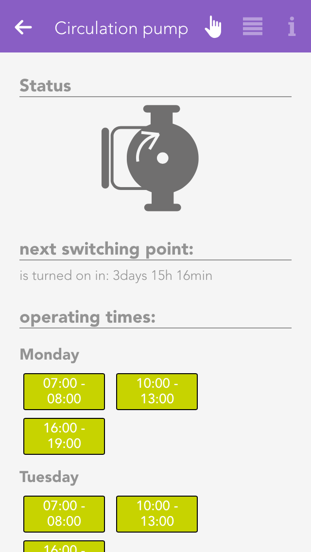
To add a new circulation pump, click on the element “add circulation pump”. The next step is to allocate a name for your circulation pump in the parameter panel. Then you can continue with the configuration (described below).
Szenen
Die Zierkulationspumpe bietet folgende Auslöser für evonHOME Szenen (Wenn...):
- Ausgeschaltet: Die Zirkulationspumpe wurde ausgeschaltet
- Eingeschaltet: Die Zirkulationspumpe wurde eingeschaltet
Die Zierkulationspumpe bietet folgende Funktionen für evonHOME Szenen (Dann...):
- Einmalig einschalten: Die Zirkulationspumpe wird zusätzlich einmalig eingeschaltet
my-PV
Die my-PV Geräte AC-ELWA und AC-THOR ermöglichen Dir mit evonHOME Deine überschüssig erzeugte Energie (z.B.: aus einem Photovoltaik-System) für die Warmwassererzeugung zu nutzen. In wenigen Schritten kannst Du nun Dein Geräte zum Betrieb mit evonHOME konfigurieren.

Du findest myPV unter "Alle Apps" - "My Pv"
Erstellen
Um Deine myPV Geräte zu integrieren, musst Du diese vorbereiten. Dazu solltest Du die IP Adresse Deines Gerätes kennen.
Das Gerät muss sich im Modus "Modbus TCP" befinden. Wie Du diesen Modus aktivierst, kannst Du in der Anleitung Deines Gerätes nachlesen.
Zudem sollte die IP-Adresse des Gerätes auf eine freie statische IP-Adresse gesetzt werden.
Falls Du Dein Warmwasser nur über das my-PV Gerät aufheizen möchtest, empfiehlt es sich, den Sicherstellungsmodus zu aktivieren.

Nach der Inbetriebnahme kannst Du durch Klick auf "Gerät hinzufügen" dein Gerät integrieren.

Durch Klick auf „Weiter“ werden die nächsten Schritte der Integration geladen. Es besteht jederzeit die Möglichkeit mittels „Abbrechen“ die Integration abzubrechen.

Im ersten Schritt ist es notwendig, das my-PV Gerät so zu konfigurieren, dass es für eine evonHOME Integration bereit ist (siehe Punkt 1).

Im nächsten Schritt ist die Eingabe der Geräte IP-Adresse erforderlich.

Im Regelfall wird der Typ des Gerätes automatisch erkannt und der Schritt 3 übersprungen. Sollte dies jedoch nicht der Fall sein, muss der Typ manuell ausgewählt werden.

In Schritt 4 muss der Name und die Örtlichkeit vergeben werden. Dieser kann jederzeit verändert werden.

Als Nächstes muss die Quelle der externen Leistungsvorgabe ausgewählt werden. Dies gibt die Soll-Heizleistung des my-PV Gerätes vor. Im abgebildeten Beispiel wird der vom Smart Meter gemessene Leistungsüberschuss, der in das Stromnetz eingespeist wird, verwendet.
Zusätzlich kannst Du entscheiden, ob die Leistungsvorgabe Deinen PV Überschuss ausregeln soll, oder Du einen Fixwert z.B. über die Logik, vorgibst.

Abschließend kann die Leistungsvorgabe konfiguriert werden. Dies ist insbesondere dann interessant, wenn mehrere my-PV Geräte verwendet werden.

Im letzten Schritt wird bestätigt, dass das Gerät erfolgreich integriert wurde.

Ist die Konfiguration abgeschlossen, erscheint das neue Gerät in der Übersicht von evonHOME.
Im Object Panel des Gerätes wird die aktuell gemessene Temperatur sowie die aktuell verwendete Leistung angezeigt.
Ein rotes "X" signalisiert einen Verbindungsverlust zum Gerät. In diesem Fall sollte die Netzwerkverbindung überprüft werden.
Konfiguration

Das Parameterpanel erlaubt Dir jederzeit die Konfiguration zu prüfen und zu adaptieren.
Hier kann die Leistungsvorgabe geändert werden oder deren Parameter eingestellt werden.
Bei my-PV Geräten ohne Drehknopf zur Einstellung der Abschalttemperatur kann diese im Parameter Panel eingestellt werden.
Bedienung

Am Operatorpanel werden Dir der aktuelle Status und die wichtigsten Informationen des Gerätes dargestellt.
Durch Aktivierung von "Manuelle Steuerung" wird die externe Leistungsvorgabe gesperrt. Die Leistung kann dann mithilfe des erscheinenden Sliders festgelegt werden.
Ist im my-PV Gerät der Sicherstellungsmodus aktiviert, wird ein Button "Sicherstellung einmalig starten" sichtbar. Durch Klick auf diesen Button wird die Sicherstellung am Gerät gestartet und bleibt bis zur Erreichung der Zieltemperatur aktiv.
Verwendung der Leistungsvorgabe:
Der Wert der externen Leistungsvorgabe wird im PV Überschussmodus über einen Regler auf 0W ausgeregelt, um ein Schwingen des Stromüberschusses zu vermeiden.
Beispiel:
Liefert der Fronius Wechselrichter einen Überschuss von 2000W, werden vom my-PV Gerät 2000W verwendet. Der Überschuss fällt dann auf 0W, was ohne Regler zu Folge hätte, dass das my-PV Gerät 0W verwenden würde, wodurch der Überschuss wieder auf 2000W springt. Dieses Schwingverhalten wird durch den Regler vermieden.
Die aktuell geregelte Leistungsvorgabe wird anschließend überprüft und begrenzt. Die errechnete Leistung wird in Folge dem my-PV Gerät zur Wärmegewinnung übergeben.
Mixer Circuit Control
The “mixer circuit control” app is an external temperature heating control loop. The “mixer circuit control” is used to configure and control 3-way heating mixer valves.
These functions are located under “all apps” – “mixer circuit control”.
Operation

Click on the element “add mixer control” to create a new mixer circuit controller. The next step is to give your mixer circuit control a name, and then you can continue with the configuration.
The operator panel displays a schematic of the control. This diagram shows you whether the pump is on (screw in the pump is green and rotates) or off. Displayed adjacently is the current temperature of the feed line and to the right the current position of the mixer valve and whether it is open or closed.
All relevant values pertaining to your mixer circuit control are displayed below this.
If your mixer valve is unreferenced, i.e. the current position of the valve is unknown, then the button “execute reference” is displayed. Clicking on it closes the valve completely; hence the current position is known. The mixer circuit control must be fully configured before a reference can be executed.
Heating Curve
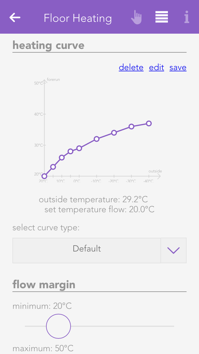
The heating curve allows you to adjust the desired temperature of the feed line as a function of the outside temperature.
There are pre-defined curves you can select from using “select curve type”. If there is no pre-defined curve that entirely suits your needs, then you can edit the pre-defined curves by clicking on “edit”. The selection then jumps to “user-defined”. If you wish to save your curve, click on “save”. Saved curves can be deleted using “delete”. When selecting points, you are limited on the one hand by the minimum and maximum feed line temperature, and on the other by the previous and subsequent point. For example, the point at 10 °C outside temperature cannot have a lower feed line temperature than the point at 15°C and a higher temperature than the point at 5°C.
If the outside temperature reaches a value outside of the curve, then the curve is continued horizontally. This means if the curve were to end on the left-hand side at an outside temperature of +20°C with a corresponding feed line temperature of +22°C, then the feed line temperature for outside temperatures higher than +20°C will remain +22°C.
To be able to process outside temperatures higher than +20°C, the cooling operation must be activated under “all apps” – “settings” – “room climate”. Warning! Cooling operation may only be activated if the heating is really able to cool, since in cooling mode, the mixer outputs are switched exactly the opposite way.
Feed Line Temperature Limitation
You can define your minimum and maximum feed line temperatures here.
Rücklauftemperatur Begrenzung

Über diese Einstellung kannst Du die maximale Temperatur, die im Rücklauf vorhanden sein darf, regulieren. Wird die eingestellte Temperatur überschritten, wird das Ventil geschlossen bis die Temperatur wieder unter dem vorgegebenen Wert liegt.
Mixer Parameters
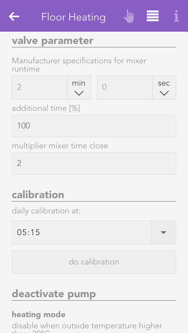
Enter the runtime for the mixer valve in seconds according to the manufacturer in “manufacturer mixer valve runtime [s]”. If the value you entered was correct, then you must now click on the button “execute reference run”. Please note that you must have previously correctly set the inputs and outputs.
The field “overrun time” lets you how much longer in percent the mixer output remains switched on when completely open or closed. This guarantees that the mixer is subsequently really completely open or closed.
Since a mixer valve normally requires longer to close than to open, you can use the “multiplier mixer closed” to define how much longer the valve needs to close than open.
Calibration Run

Since there is always a certain error when opening and closing the valve, a calibration run must be run daily. All you have to do is set the desired time for this to occur and the rest is done automatically.
Inputs
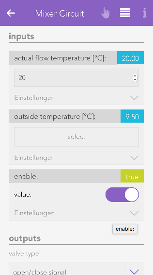
Feed line actual temperature
Select the input here that measures the actual temperature of the feed line.
Outside temperature
Select here the input used to measure the outside temperature. The standard setting is located in “system” – “house status” – “outside temperature”.
Release
Select the main switch for the mixer control. This input is used to activate or deactivate the entire control.
Outputs
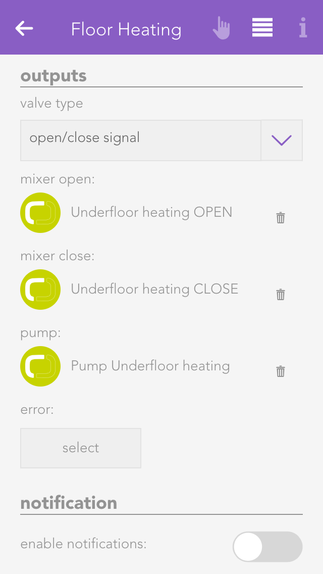
Valve Type
The used valve type is chosen here. The options are analog with "0-10V signal" and digital "open/close signal".
Valve
(With valve type "0-10V signal")
Select the analog output, which will be used for the valve control.
Mixer open
(With valve type "Auf/Zu signal")
Select here the output used to open the mixer valve.
Mixer closed
(With valve type "Auf/Zu signal")
Select here the output used to close the mixer valve.
Pump
Select the output used to connect the mixer pump.
Fault
Select an output to be switched if there is a fault.
Pumpe deaktivieren

In diesem Abschnitt kannst Du die automatische Abschaltung der Pumpe einstellen, wenn von Dir festgelegte Temperaturen über- oder unterschritten werden.
Absenkbetrieb

Hier kann der Absenkbetrieb konfiguriert werden. Bei aktiviertem Absenkbetrieb wird die Heiz- oder Kühltemperatur/leistung um den verknüpften Wert verringert.
Extended Configuration
The extended configuration allows you to configure all the components of your mixer control extra. Simply click on “edit”. Exercise caution, particularly when adjusting the controller parameters.
Below this, you can adjust the sample time and minimum error.

Sample time
This is the time period when a new position of the valve is calculated (standard 10s).
Minimum error
The position of the valve is only adjusted if there is a difference between desired and actual temperature of the feed line. If the difference (error) is larger than this value, then the position of the valve is changed.
Activate notification
If you wish to receive a notification of a fault condition, then activate this option.
Logic
The logic app enables you to execute complex operations for which there is no app. For example, this could be controlling the ventilation of the WC, controlling a light transformer etc. If you wish to use logic, then you should already have a basic understanding. If you are new to the area of logic, exercise caution when using this feature.

The logic app is located under “all apps” – “logic”.
Logic Program
To create a logic sequence, you first need a logic program. This is comparable to a network in PLC programming. A program contains logic elements that you can use for your controller. For example, if you have a controller for the WC ventilation and one for a light transformer, then you can create an individual program for every controller.
Create

To create a logic program, open “logic” and select “add program”. This opens the operator panel for the logic program. You must first allocate a name to your program and optionally a room for it.
Parameter

The operator panel for the logic program contains an item “parameter” where all parameters available to rapidly configure the program are listed (parameters are described in the chapter data elements). The values of these parameters are not lost if a controller fails.
Status
The item “status” displays a diagram that shows you the time required to execute this program.
Control Command And Status Text

Every logic program can contain a control command and a status text. You can select a data element of type bool for the control command and a data element of type string (text). To do this, go to the parameter panel and select “choose control command and status text”.
The control command is intended to activate and deactivate the logic program via the object panel. You can toggle the control command via the icon on the left-hand side of the object panel.
The status text is displayed in the object panel under the name of the program. An example would be “ventilation will be switched off in 2 mins”.
Edit Logic

If you want to edit the logic in this program, click on the button “edit” in the parameter panel under the item “logic”.
Input und Output

Each logic program allows you to define in- and outputs, which are shown in the linkpanel of a program. Defined in- and outputs can then be linked to values of other evonHOME apps.
This makes it possible to create interfaces for your logic program which make it easy for you to integrate it without the need to modify or edit the underlying logic construct. It is also very useful if you want to reuse it for different purposes as you only have to adapt the linked values.

To define an in- or output for your logic program, select a data element and change the type to "Input" or "Output".
It will then be listed in the linkpanel of your logic program and can be connected to other apps/values.
Import/export
If you wish to save the logic program, you can do this via the button “export” in the parameter panel under the item “import/export”.
To import a logic program, click on the button “import” (directly under the “export” button). Note that any existing logic is overwritten by the logic in the imported program. Furthermore, if logic elements were linked across programs prior to export, after importing, the links no longer exist.
Color And Icon
You can allocate a colour and icon to your logic program. Do this in the parameter panel under the item “settings” by clicking on the current colour or icon.
Szenen
Die Logik bietet folgende Auslöser für evonHOME Szenen (Wenn...):
- (Datenbaustein Zahl) Zählerstand wurde vergrößert: Der Wert im Datenbaustein wurde erhöht
- (Datenbaustein Zahl) Zählerstand wurde verkleinert: Der Wert im Datenbaustein wurde verringert
- (Datenbaustein Text): Text wurde geändert: Der Text im Datenbaustein wurde geändert
- (Datenbaustein Bool): Steigende Flanke: Der Wert wurde auf logisch 1 (true) gesetzt
- (Datenbaustein Bool): Fallende Flanke: Der Wert wurde auf logisch 0 (false) gesetzt
Die Logik bietet folgende Funktionen für evonHOME Szenen (Dann...):
- (Datenbaustein Zahl) Wert setzen: Der Wert im Datenbaustein kann beliebig manipuliert werden
- (Datenbaustein Text): Wert setzen: Der Text im Datenbaustein kann beliebig manipuliert werden
- (Datenbaustein Bool): Aktivieren: Der Wert wird auf logisch 1 (true) gesetzt
- (Datenbaustein Bool): Deaktivieren: Der Wert wird auf logisch 0 (false) gesetzt
Logic Elements
Elements are all logic elements that you can add to a logic program (AND, OR, etc.)
Create

To create a logic element, you must first be located in the logic program. If not, open the logic program and select the item “edit logic” in the parameter panel. Then add new logic elements to the program using “add function”. To do this, click on the corresponding element.
Element Colour
If a logic element has an error, or if it is simply not activated, then you can recognize this due to the colour of the element.
Green
The element is working fine.
Orange
The output of this element is being simulated.
Grey
The element does not have a fault, but it is deactivated.
Red
The element has a fault: either an input has no value, or the output it is linked to no longer exists.
Connecting Elements
The operator panels for each logic element (except for data elements) are all constructed using the same principle. The first item is the setting (if available), then the inputs, then the output.

This shows you the selection of an input.
The button “select” lets you select the output of a different logic element that you wish to connect to this input.
The checkbox under “invert” lets you invert the input (if it is of type bool).
The checkbox under “fixed value” lets you allocate a fixed value to the input. This means that if you activate this checkbox, the type bool displays a checkbox in the centre with the text “value”. The state of the input can be controlled using this value. If you activate this checkbox for an input of data type number or string, then an input field appears where you can enter the desired value.
Data Elements
Data elements are intermediate stores for values. This means that data elements can be described by other logic elements by selecting this data element at the output (however only if both are of the same type). Data elements can also be linked with inputs of other logic elements. Every data element has the option “parameter” in the operator panel. If you have activated this option, then you can see this data element in the operator panel of the corresponding logic group and you can change it from there. This has the advantage that you do not always have to have the logic program open to change a value. Parameters also means that the value of a data element remains even if the controller were to fail.
You can change the value of any data element via the object panel. You can do this on the left-hand side of the object panel for types bool and number, and on the right-hand side via the input field for type string.
AND

The element “AND” is a classical AND operator. This means the output is set to true as soon as ALL inputs are true. This element can have between 2 and 6 inputs. The number of inputs can be changed via the operator panel using the buttons “add pin” and “remove pin”.
OR

The element “OR” is a classical OR operator. This means the output is true as soon as at least one input is true. This element can have between 2 and 6 inputs. The number of inputs can be changed in the operator panel using the buttons “add pin” and “remove pin”.
Compare
The compare function works by comparing the values present at the two inputs and switches the output accordingly.
You can change the following settings in the operator panel:

Type
Select the type of comparison
Hysteresis
If you require hysteresis, you can define it here.
Sample time
This is the time for which the comparison must be fulfilled for the output to be switched to true.
Time Relay
The time relay lets you delay an output switching on or off, or leave it switched on for a certain time.
The time relay has two types that you can configure under “select used times”.

Delay switching on/off
If the input is true, the output is only set to true after the selected ON time delay. If the input jumps from true to false, the output is set to false after the selected OFF time delay.
Switch on delay and duration
This enables the option “input as flank”. If you have not activated this option, then the input must be true for at least the switch on delay time in order for the output to be set true for the defined duration and after this duration (independently of the input) reset to false. If you have activated this option then a flank is sufficient on the input and the output is set to true for the defined duration and then reset to false.
Time Measurement
Time measurement is represented by a stopwatch. Time measurement can be started, stopped and reset via inputs “activated” and “reset”.

If the input “activated” moves from false to true, the stopwatch starts. If the input “activated” moves from true to false, the stopwatch stops, if “auto reset” was NOT activated.
If “auto reset” is activated, then the stopwatch is reset when the input “activated” moves from true to false.
The input “reset” resets the stopwatch. This only works if “auto reset” has not been activated.
Value Allocation
Mit der Wertzuweisung kann ein beliebiger Wert dem Ausgang zugewiesen werden.

The value on the input E1 is written unchanged to the output if “activated” is true.
Counter
The counter can increase, decrease or reset a numerical value to 0.

The input “up” increments the counter by one when the input changes from false to true, the input “down” decrements the counter by one and “reset” resets the counter to 0.
Flank Recognition
Flank recognition allows rising and falling edges to be evaluated. This means that if the selected flank appears on the input, then the output is set to true for one cycle and then reset to false.

The type of flank can be selected in the operator panel under the item “settings”.
Function Generator
The function generator enables periodic square wave signals to be generated.

As soon as the input “activated” is true, the function generator is started and generates a periodic square wave signal on the output.
“TOn” can be used to adjust how long the square wave signal is true and “TOff” how long it is false.
Function
A function element is used to carry out mathematical calculations. “A1” must contain the desired calculation.

The variables E1 to E6 can be used for the calculation, e.g. A1 = 2*E1 + E2.
As soon as the input “activated” is active, the calculation will be carried out. The buttons “add pin” and “remove pin” can be used to add up to 6 inputs. The following shows link shows you which operations are possible:
Documentation- Functions(https://developer.mozilla.org/de/docs/Web/JavaScript/Reference/Global_Objects/Math)
Reset

For as long as the input is true, the output of the reset element will be set to false.
Set

For as long as the input is true, the output of the set element will be set to true.
SR Flip Flop
The SR flip flop is used to set and reset an output. If the input “set” is true, then the output is true. If the input “reset” is true, the output is false. If both inputs are true, then the output is false. If both inputs are false, the output is stored, meaning it remains in this state until the input is true again.
Text Block
The text block is used to create any text string you want.

1 to 6 inputs (E1 – E6) can be created using the buttons “add pin” and “remove pin” and the text from these inputs are then strung together.
For example, if the text for E1 is “It is now ” and the text for E2 is the current time (use the button “select” and under “system” then “time”), then the following text string will be created “It is now 17:00”.
PI Controller

This is a clocked PI controller where you supply demand value, actual value and clock.
The settings for the PI controller are located in the parameter panel.
Examples
WC Ventilation
Task
If the light in the WC is switched on, then the ventilation should be switched on 15 seconds later (the ventilator must be connected to a digital output) and run for one minute after the light has been switched off. If the light is switched off before the ventilator is switched on, the ventilator should not be activated.
Solution
First open the app “logic” and create a logic program via “add program”.
Give the logic program the name WC-ventilation and select the room WC.
Open the logic program via the button “edit”. Use the “add function” to add the function time relay. This relay is red, meaning that it isn’t yet working, because there are no inputs.
Now open the time relay. Since the output should be switched on after 15 seconds, you will need a delay of 15 seconds. Change the switch on delay to a fixed value and enter the value 15. Do the same for the switch off delay, except instead of 15, use the value 60, since the ventilation is only meant to run for 1 minute (= 60 seconds) after the light has been switched off.
Now you need to link inputs and outputs. Select input E1 using the button “select” and navigate to the lights, select the WC light and select “light on”. In the object panel of the time delay, you can now see the current value of the light and how it changes when the light is switched on and off. Now all you need to do is connect the output of the time relay with the digital output. To do this, click on “select” under “output” and navigate to the digital outputs. Once there, select the desired output and click on “set value”.
Now you can test your WC ventilation and see if everything is working fine.
Light Transformer
Task
There are 4 lights and 1 light transformer available. The light transformer is connected to a digital input. As soon as at least one light is switched on, the light transformer must be switched on. If no lights are switched on, the light transformer must also be switched off.
Solution
The first thing to do is open the app “logic” and create a logic program via “add program”.
Give this logic program a name “light-trans”.
Next, open the logic program using the button “edit”. Use the button “add function” to add an OR. This OR is red meaning that it is not currently functioning, because it has no inputs.
Now open the OR and add two inputs using the button “add pin”. These four inputs must now be linked with the four lights via the button “select” by selecting “light switched on” for each light. The OR is now green, because all inputs are linked. Finally, you need to connect the digital output of the transformer with the OR. Do this by clicking on “select” under “output”, open the digital output there and select “set value” for the desired digital output.
The logic should now work as desired.
Ventilation Control
Task
You measure humidity in a room and want to switch on the ventilation as soon as the humidity has reached a certain value.
Solution
To do this, the humidity sensor must be connected to an analog input of an analog module and configured accordingly (to do this, see chapter “Analog Input”). The ventilation must be connected to the output of a digital module.
Next, create a logic program in the app “logic” using “add program”. Give the program a meaningful name (e.g. fan control) and if wish, allocate a room. Then open the parameter panel and select “edit” under “edit logic”. Insert a compare function via “add function”.
Now open the operator panel of the compare function. Under the item “settings”, first select for “type” the value “greater than” (since the fan is to be switched on when the humidity is GREATER than a certain value). You can configure the hysteresis for the compare function as you feel is necessary. In this example, select 5 for the hysteresis. The sample time can be left at 0. Now the compare function is correctly configured.
The inputs and output now need to be connected. Select the analog input you connected the humidity sensor to under “inputs” for “E1”. For “E2” enter the value above which the fan is to be switched on. In this example select 80. Now select the digital output you connected the fan to using the button “select” under “output”.
The ventilation control is now complete. If you want, you can change the hysteresis and the sample time as you require.
Daikin
Über die Daikin App lassen sich kompatible Daikin Klimageräte in evonHOME einbinden, über die Visualisierung steuern und über Szenen mit anderen Funktionen verknüpfen.
Kompatible Geräte kannst Du unter dieser Adresse einsehen:
daikin.at/de_at/produktgruppen/regelung/online-controller/anschliessbare-geraete.html

Du findest die Anwendung unter 'Alle Apps' - 'Daikin'.
Erstellen
Um Dein Daikin Klimagerät mit evonHOME verbinden zu können, benötigst du einen Daikin Online Controller. Informationen darüber findest Du unter folgender Adresse: daikin.at/de_at/produktgruppen/regelung/online-controller.html

Um ein in Dein Netzwerk eingebundenes Daikin Klimagerät hinzuzufügen wähle "Daikin hinzufügen" .

Im nun erscheinenden Popup werden automatisch alle gefundenen Daikin Geräte gelistet. Sobald Dein Klimagerät in der Liste erscheint, kannst Du es direkt auswählen. Es wird nun im System hinzugefügt und kann sofort verwendet werden.
Sollte Dein Klimagerät nicht im Netzwerk gefunden werden hast Du ausserdem die Möglichkeit die Suche erneut zu starten, oder die Konfiguration manuell vorzunehmen. In diesem Fall wird eine Daikin Gerät hinzugefügt, bei dem Du die IP Adresse selbst eintragen musst.
Szenen
Die Daikin App bietet folgende Auslöser für evonHOME Szenen (Wenn...):
- Wurde ausgeschaltet: Das Klimagerät wurde über evonHOME ausgeschaltet
- Wurde eingeschaltet: Das Klimagerät wurde über evonHOME eingeschaltet
Die Daikin App bietet folgende Funktionen für evonHOME Szenen (Dann...):
- Ausschalten: Das Klimagerät wird ausgeschaltet
- Betriebsmodus setzen: Ein frei auswählbarer Betriebsmodus (Heizen, Kühlen,...) wird als Vorgabe an das Gerät gesendet
- Einschalten: Das Klimagerät wird eingeschaltet
- Einschalten mit Optionen: Das Klimagerät wird mit verschiedenen frei wählbaren Parametern eingeschaltet
- Luftstromrichtung setzen: Eine frei auswählbare Luftstromrichtung wird als Vorgabe an das Gerät gesendet
- Lüftungsstufe setzen: Eine frei auswählbare Lüftungsstufe wird als Vorgabe an das Gerät gesendet
- Soll Temperatur setzen: Ein frei wählbare Soll-Temperatur wird an das Gerät gesendet
Konfiguration

Neben der Vergabe eines Namens und der Zuordnung zu einem Raum, kannst Du hier auch die IP Adresse eingeben. Solltest Du Dein Daikin Klimagerät manuell hinzugefügt haben oder sich die IP Adresse später ändern, musst Du diese hier eintragen bzw. aktualisieren.
Bedienung

Wurde das Daikin Klimagerät erfolgreich in Dein evonHOME eingebunden, stehen Dir mehrere Bedienelemente zur Verfügung.
Du kannst die Temperatur einstellen, das Gerät ein-/ausschalten und den Betriebsmodus umschalten.
Außerdem lässt sich der Lüftungsmodus von "Automatisch" auf "Manuell" oder "Silent" (falls Dein Daikin Gerät dies unterstützt) ändern. Im manuellen Modus kannst du die Lüfterstufe einstellen.
Zusätzlich lässt sich noch die Luftstromrichtung anpassen.
Alle Einstellungen lassen sich auch über Szenen steuern. So kannst Du z.B.: die Lüftungsstufe oder Temperatur ändern, sobald Deine festgelegten "Wenn"-Bedingungen erfüllt sind.
Camera
The app “Camera” lets you integrate your evonCAM into your system.
The Camera app is located under “all apps” – “Camera”.
Create
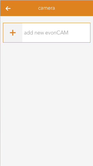
In order to create a camera, click on the box “add new evonCAM” inside the app.
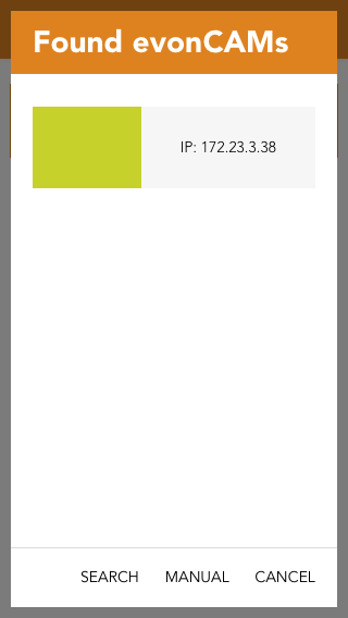
All found evonCams including a preview image will now be listed in the popup which appears. Once your camera shows up on this list you can select it and it will be added to your system and is ready to be used.
If your camera ist not immediately found in your network, you have the option to restart the search or to configure it yourself. In this case a camera will be added for which you have to add the required settings (IP address, username, password).
Configuration
To correctly configure the camera, enter the IP address of the camera into your browser.

If you followed the steps to integrate your evonCAM and the camera was found and added to your system, no further configuration is required.
In case you chose the manual configuration (e.g. because the camera was not automatically found in your network), you can change or adapt the required settings at any time in the ParameterPanel of the camera.
This can also be necessary, when you make changes to the standard username/password or the IP address.
If you change the settings (username/password) of the camera (via its webinterface) the app or browser may ask you to enter the new credentials.
After you did this, it is important to go to the ParameterPanel of the camera and update those settings there, otherwise you will regularly be asked to enter the new credentials.
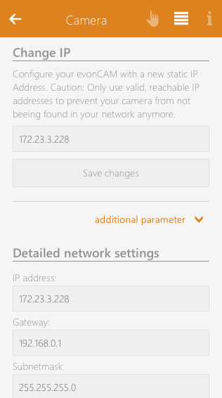
You can also change the IP of your camera to a specific static address. Changing settings here will write the new network configuration to the camera which will then restart with the new settings applied.
If you change the IP address, other required network settings (gateway and subnetmask) will automatically be taken from the current evonHOME controller network configuration. If you want more control over this settings there is also an extended form available under the additional parameter button.
Operation
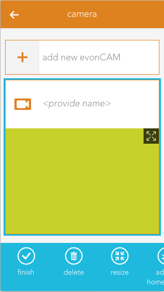
The camera panel supports two different sizes. If you hold down your finger (cursor+left mouse button) on the panel for some seconds a bar will appear on the bottom of your screen, which gives you the ability to change the size from small to large.
The large size supports displaying the current camera video inside the panel. Like most other panels, you can add this to your favorites on the start screen which will allow you to always see the current camera image.
With the icon located on the top right corner of the camera image, you can open a popup with bigger view of the video stream, which is well suited for bigger screen sizes like tablets.
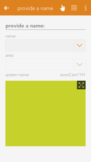
The camera OperatorPanel displays the current video/image if the correct credentials are added in the settings. You can also open a popup containing a bigger sized version of the camera image by clicking the icon in the top right corner of the image.
If you did not enter a name for the camera yet, the associated input field will also appear here.
Trending
Mit der App "Trending" kannst Du verschiedene Werte Deines evonHOMEs aufzeichnen und diese in einem Diagramm darstellen.

Du findest die Trending App unter Alle Apps.
Erstellen

Um ein neues Trending Panel zu erstellen, navigiere zur App und wähle 'Trending hinzufügen'.
Konfiguration
In den Einstellungen kannst du konfigurieren welche Werte aufgezeichnet werden sollen, wie lange diese aufgezeichnet werden sollen und wie diese im Diagramm dargestellt werden sollen.

Einstellungen
Diagramm Typ
Der Diagramm Typ entscheidet ob das Diagramm als Flächen- oder Liniendiagramm angezeigt wird.
Werte dauerhaft speichern
Wenn diese Option aktiviert wird werden die aufgezeichneten Werte über den Neustart hinweg gespeichert.
Aufzeichnungsintervall
Das Aufzeichnungsintervall bestimmt in welchen Abständen ein neuer Wert vom Trend aufgezeichnet wird. Gemeinsam mit der Anzahl an Aufzeichnungspunkten ergibt sich der Zeitraum über den aufgezeichnet wird.
Maximale Anzahl an Aufzeichnungspunkten
Die maximale Anzahl an Aufzeichnungspunkten entscheidet wie viele Punkte maximal aufgezeichnet werden können. Wenn diese Anzahl überschritten wird werden ältere Punkte gelöscht. Der Wert kann von 1 - 10.000 eingestellt werden. Gemeinsam mit dem Aufzeichnungsintervall ergibt sich der Zeitraum über den aufgezeichnet wird.
Damit die Einstellungen übernommen werden muss der Button "Einstellungen übernehmen" betätigt werden.

Variablen
Es können insgesamt 8 Werte ausgewählt werden welche vom Trend aufgezeichnet werden sollen. Durch den Button "hinzufügen" können neue Werte hinzugefügt werden.
Werte in Diagramm anzeigen
Wenn diese Option aktiviert ist wird der Wert im Diagramm angezeigt.
Alias
Wenn diese Option aktiviert ist kannst du einen eigenen Namen für den Wert angeben, welcher dann im Diagramm angezeigt wird.
Farbe
Hier kannst du eine eigene Farbe auswählen, in welcher dann der Wert im Diagramm angezeigt wird.
Bedienung
Die Ansicht der Trending App unterstützt drei verschiedene Größen. Wenn du für einige Sekunden die Auswahl auf der Trending App (mit dem Mauszeiger Linksklick oder mit dem Finger gedrückt halten) erscheint am unteren Bildschirmrand ein Panel, bei dem Du unter anderem die Möglichkeit hast die Größe zu ändern.

In der kleinsten Ansicht wird dir nur der Name und der Raum des Trends angezeigt. Bei klick auf die Ansicht öffnet sich die Bedienung und die Einstellungen.

In der weiten Ansicht wird Dir zusätzlich das Diagramm angezeigt.

In der größten Ansicht hast du zusätzlich die Möglichkeit das Diagramm in einer größeren Ansicht zu betrachten indem Du auf das Pfeil Symbol am rechten oberen Rand klickst.
Durch einen Klick auf den Namen des Trends öffnet sich die erweiterte Bedienung.

In der Bedienung des Trends siehst Du das Diagramm mit den aufgezeichneten Werten. Zusätzlich kannst du eine größere Ansicht über das Pfeil Symbol in der rechten oberen Ecke öffnen. Im unteren Bereich des Diagramms wird Dir die Legende angezeigt, hier kannst Du temporär einzelne Werte ausblenden.
Denon
This section contains information on using connected DENON devices.
Denon lets you play music throughout your house, whether from a USB stick, music server, Internet radio, iPod, AUX or online music.
The Denon app is located under “all apps” -“Denon”.
Currently, only the DENON DRA-N4 amplifier is supported by evonHOME.
Operation
Volume
You can change the volume via the “+” and “-“ buttons, or use the slider.
Source
Use this to determine where your music is to come from and see the Denon display below it. Navigate around your Denon using the 4 arrows and the enter button.
Favourites
Add the current programme to your favourites list using the button “add to favourites” so that you can find it again quickly. All your favourites are displayed in a list below this.
ON/OFF
Switch your Denon on an off.
Status
Shows which music source is currently active, Internet music, iPod etc. and shows the current IP address.
In the parameter panel, you can also define whether this Denon is to be switched with the universal scenes or not “remove from universal scene”) and how loud the Denon can be allowed to be.
Szenen
Die Denon App bietet folgende Auslöser für evonHOME Szenen (Wenn...):
- Play: Die Wiedergabe wurde mit Play gestartet
- Pause: Das Wiedergabe wurde mit Pause gestoppt
Die Denon App bietet folgende Funktionen für evonHOME Szenen (Dann...):
- Ausschalten: Das Gerät wird ausgeschaltet
- Einschalten: Das Gerät wird eingeschaltet
- Play: Die aktuelle Wiedergabe wird gestartet
Fronius
The "Fronius" app allows you to integrate your Fronius system into your evonHOME.

The Fronius app ist located under 'all apps' - 'Fronius'.
All limits, which can be configured in the Fronius app, can also be used as triggers for scenes.
Create
To integrate your Fronius system, please follow the steps below.
(You will need the IP Adress of your PV-system for this)
Open the Fronius app an choose 'add'.
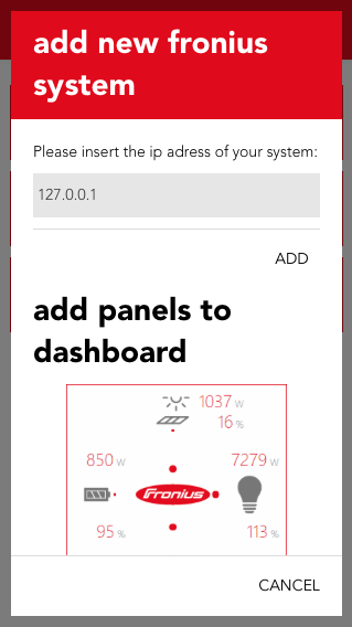
Enter the IP address of your PV system in the now appearing popup.
Confirm it with the button 'add'.
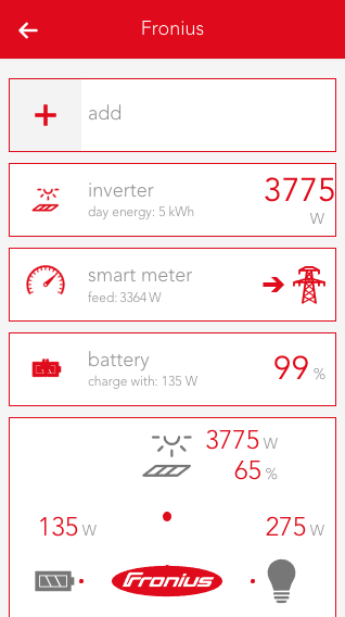
Once entered successfully, all installed elements of your PV system will be shown.
Szenen
Die Fronius App bietet folgende Auslöser für evonHOME Szenen (Wenn...):
-
(Inverter) Leistungslimit 1 überschritten: Das konfigurierte Leistungslimit 1 wurde überschritten
-
(Inverter) Leistungslimit 2 überschritten: Das konfigurierte Leistungslimit 2 wurde überschritten
-
(Inverter) Leistungslimit 3 überschritten: Das konfigurierte Leistungslimit 3 wurde überschritten
-
(Inverter) Leistungslimit 1 unterschritten: Das konfigurierte Leistungslimit 1 wurde unterschritten
-
(Inverter) Leistungslimit 2 unterschritten: Das konfigurierte Leistungslimit 2 wurde unterschritten
-
(Inverter) Leistungslimit 3 unterschritten: Das konfigurierte Leistungslimit 3 wurde unterschritten
-
(Smart Meter) Bezug vom Netz begonnen: Der Strombezug vom Energieversorger-Netz hat begonnen (Es wird aktuell mehr Energie verbraucht als erzeugt)
-
(Smart Meter) Einspeisung ins Netz begonnen: Die Stromeinspeisung in das Energieversorger-Netz hat gestartet (Es wird aktuell mehr Energie erzeugt als verbraucht)
-
(Smart Meter) Netzbezugs Grenzwert 1 überschritten: Der konfigurierte Grenzwert 1 für den Netzbezug wurde überschritten
-
(Smart Meter) Netzbezugs Grenzwert 2 überschritten: Der konfigurierte Grenzwert 2 für den Netzbezug wurde überschritten
-
(Smart Meter) Netzbezugs Grenzwert 3 überschritten: Der konfigurierte Grenzwert 3 für den Netzbezug wurde überschritten
-
(Smart Meter) Netzbezugs Grenzwert 1 unterschritten : Der konfigurierte Grenzwert 1 für den Netzbezug wurde unterschritten
-
(Smart Meter) Netzbezugs Grenzwert 2 unterschritten : Der konfigurierte Grenzwert 2 für den Netzbezug wurde unterschritten
-
(Smart Meter) Netzbezugs Grenzwert 3 unterschritten : Der konfigurierte Grenzwert 3 für den Netzbezug wurde unterschritten
-
(Smart Meter) Netzeinspeisungs Grenzwert 1 überschritten: Der konfigurierte Grenzwert 1 für die Netzeinspeisung wurde überschritten
-
(Smart Meter) Netzeinspeisungs Grenzwert 2 überschritten: Der konfigurierte Grenzwert 2 für die Netzeinspeisung wurde überschritten
-
(Smart Meter) Netzeinspeisungs Grenzwert 3 überschritten: Der konfigurierte Grenzwert 3 für die Netzeinspeisung wurde überschritten
-
(Smart Meter) Netzeinspeisungs Grenzwert 1 unterschritten: Der konfigurierte Grenzwert 1 für die Netzeinspeisung wurde unterschritten
-
(Smart Meter) Netzeinspeisungs Grenzwert 2 unterschritten: Der konfigurierte Grenzwert 2 für die Netzeinspeisung wurde unterschritten
-
(Smart Meter) Netzeinspeisungs Grenzwert 3 unterschritten: Der konfigurierte Grenzwert 3 für die Netzeinspeisung wurde unterschritten
-
(Batterie) Mindestladung 1 überschritten: Der konfigurierte Wert der Mindestladung 1 wurde überschritten
-
(Batterie) Mindestladung 2 überschritten: Der konfigurierte Wert der Mindestladung 2 wurde überschritten
-
(Batterie) Mindestladung 3 überschritten: Der konfigurierte Wert der Mindestladung 3 wurde überschritten
-
(Batterie) Mindestladung 1 unterschritten: Der konfigurierte Wert der Mindestladung 1 wurde unterschritten
-
(Batterie) Mindestladung 2 unterschritten: Der konfigurierte Wert der Mindestladung 2 wurde unterschritten
-
(Batterie) Mindestladung 3 unterschritten: Der konfigurierte Wert der Mindestladung 3 wurde unterschritten
Beachte, dass es sich bei den Auslösern von Szenen nur um Ereignisse handelt. Ein Ereignis wird nur zu einem kurzen Zeitpunkt aktiv (z.B.: Bezug vom Netz hat begonnen) und kann zu diesem Zeitpunkt verwendet werden um andere Funktionen auszulösen (z.B: Heizstab Boiler ausschalten). Zum Erstellen von komplexeren Abläufen bietet sich die evonHOME Logik an.
Elements
If you integrate a Fronius system, every installed element (which is supported by evonHOME) of your PV system will be displayed.
Additionally the Dashboard of the Fronius app can be extended with more panels.
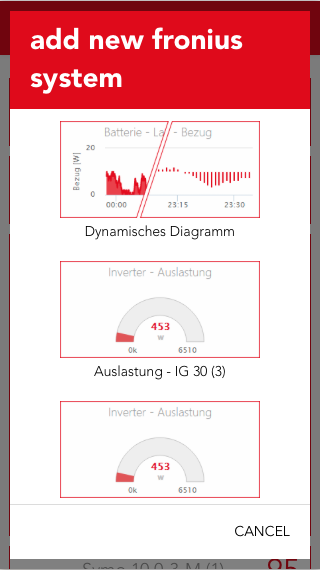
Once a PV system is integrated, you can choose to add additional panels by using the 'add' button.
You can choose between 'My Fronius', an overview about the current energy flow in your system, "Efficiency" (of the inverter), “Energy“, "Supply" and "Phase Distribution".
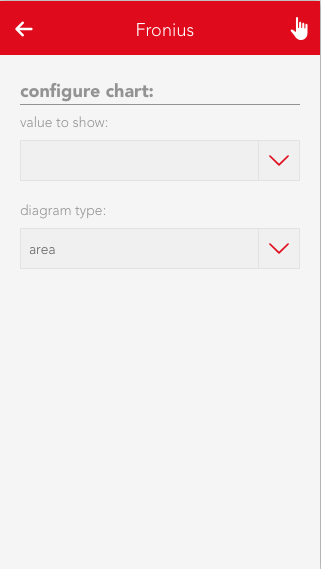
There is also a dynamic diagram available, which can be customized by the user. It allows you to choose between different values and diagram types.
All panels can be added to the home screen by selecting them with a long click/press.
Inverter

Operation
The most important values are displayed in the first part of the detail view (Operator Panel).
Additionally, the utilization and energy values for year, month and week will be shown in a diagram.
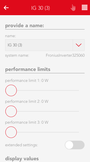
Configuration
The second part of the detail view (Parameter Panel) allows you to view detailed values and and adjust limits. Three power limits can be set which will trigger an event once exceeded or below the set value.
Detail values
Lists values which can be used by an inverter in the system.
Scenes
The inverter offers an event for the power limits 1,2 and 3 in case they are exceeded (above/below).
Smart Meter
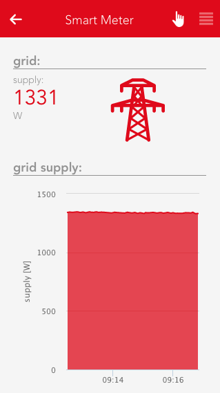
Operation
The operator panel of the Smart Meter displays the current feed-in/supply to or from the power grid and presents them in an area diagram.
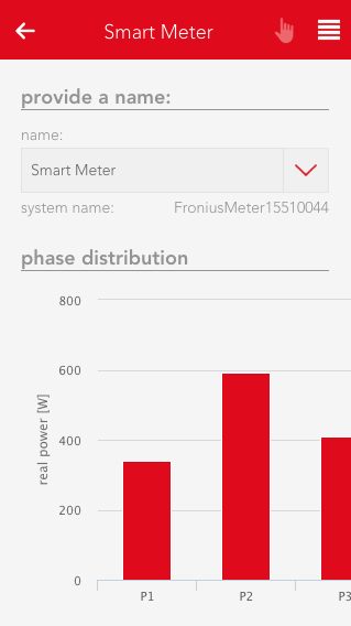
Configuration
The parameter panel displays the phase distribution in a bar chart and allows you to adjust feed-in/supply limits for he power grid, which will throw an event once exceed (below/above). In addition, all detail values of the Smart Meter are displayed.
Detail values
Shows values which can be used by a Smart Meter in the system.
Scenes
The Smart Meter offers events for feed-in/supply to or from the power grid in case they are exceeded (above/below).
Battery

Operation
The operator panel displays the current charging/discharging rate (in watt) and the current battery power level.
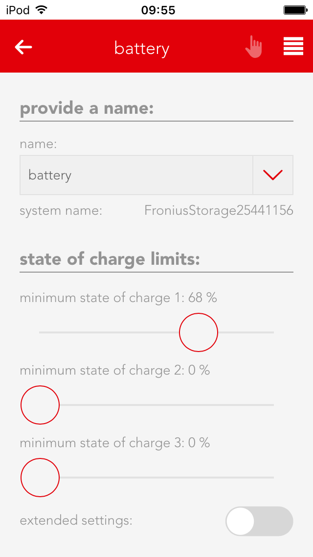
Configuration
The parameter panel allows you to adjust the minimum charging level, which will trigger an event in case it is exceed (above/below), and to view the detail values of the battery.
Detail values
Shows values which can be used by a battery in the system.
Scenes
The battery offers events for exceeding (above/below) the minimum charging limit.
TCP Client
The TCP Client app allows you to communicate with TCP-compatible devices (TCP clients). Among them are devices like beamers, TVs and many more. Additionally, you can use a gateway (TCP to serial port) to send commands to different devices with a serial port.

The TCP Client app is located under “all apps” – “TCP Client”.
Create

To create a new TCP Client, navigate to the app and choose 'add TCP client'.
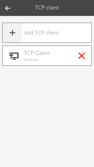
On every TCP Client, there is a symbol which shows you if there ist a working connection to the desired device. As you have to configure every new TCP Client first, the symbol will display a red X.

Before the TCP Client can communicate, you have to enter a valid IP address in the settings. To do so, open the Parameter panel of your newly created TCP Clients and enter the IP address and the port of the desired device.

If the IP address and port are correct and a successful connection could be established, you will see a green checkmark in the display of the TCP Client after some seconds.
Configuration
The settings of the TCP Client allow you to configure new commands and events, which can be linked in scenes.
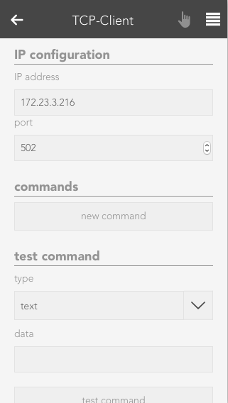
IP configuration
The IP address and port of the device for which you want your TCP Client to establish a connection to should be entered here. This settings should be the first configuration you make after creating a new TCP Client. The Operator Panel will then tell you if your connection is working.
Commands
If you want to create a new command, you can do this here by using the 'new command' button. Choose a name and the data which should be send. You can decide between simple text or hex values. Additionally, you can also decide whether you expect a specific answer and choose between text or hex values.
Test command
If you just want to test a command, you can do this here. The result will then be displayed beneath the 'test command' button.
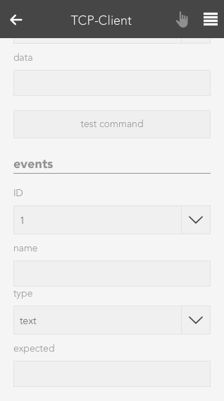
Events
There are some devices, which may frequently send data, without the need for a explicit request (e.g. via a command). For such use cases, every TCP Client has 3 events. For each event, you can set what data you are expecting and their type (text or hex). If an expected event occurs this event will be triggered and can be linked to when creating a Scene.
Operation
The Operator Panel of the TCP Client displays the current status of the client, allows you to send preconfigured commands and shows you a list of recently received data.
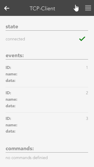
State
The current status of the TCP Client will be shown here.In case there are any problems with the connection to the desired device or you haven't entered a correct IP address yet, a red X will be displayed.
Events
Every TCP Client allows you to create 3 events, which are triggered when the conditions meets. You can then link to those events in created scenes (inside the Scene app) and use them as triggers. Configured events will be displayed in this list.

Commands
All commands you have created are listed here. You can trigger or delete each one.
Last received data
This list will display recently received data. You can switch between a 'text' or 'hex' view.
Szenen
Der TCP Client bietet folgende Auslöser für evonHOME Szenen (Wenn...):
- Ereignis 1 ausgelöst: Das konfigurierte Ereignis 1 wurde ausgelöst
- Ereignis 2 ausgelöst: Das konfigurierte Ereignis 2 wurde ausgelöst
- Ereignis 3 ausgelöst: Das konfigurierte Ereignis 3 wurde ausgelöst
- Erwartete Daten vom Befehl empfangen: Die konfigurierten erwarteten Daten nach Absetzen des Befehls wurden empfangen
Detector
The Detector app allows you to use a digital input for alarms/notifications. This can be useful in cases like when you want to connect a fire alarm to your evonHOME.
The Detector app is located under “all apps” – “Detector”.
Create
To create a Detector, you will need a digital module ("evonHOME Digital 1180" or "evonHOME Digital 1344") with an digital input. Then, follow these steps:
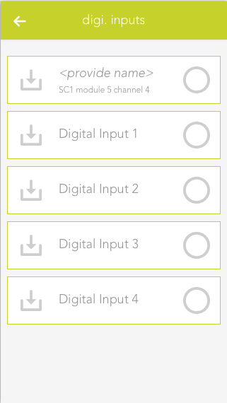
Navigate to the app 'Digital Inputs', which you can find under 'All Apps'.
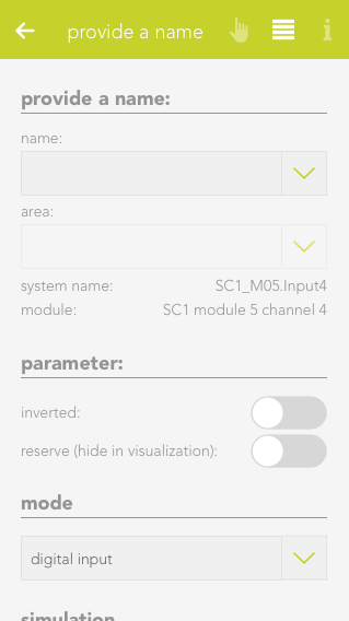
Select the desired digital input, which you want to use as a Detector.
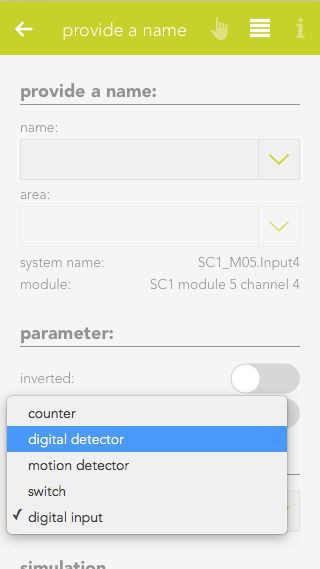
Navigate to the settings of the chosen digital input and change its mode to 'Detector'.
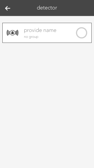
The Digital Input changed into a Detector and can now be found in the 'Detector' app.
Configuration
Each Detector allows you to configure the triggered alarms. Here you will find the description about all available options.
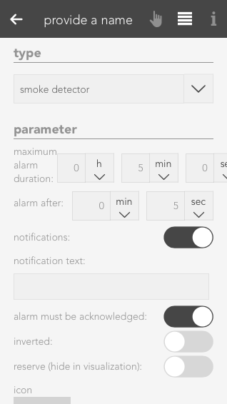
Type
This are pre configured settings for different use cases. Each one comes with a predefined notification text, settings and specific icon.
Alarm after
Defines the timespan for which a signal has to be active on the digital input to trigger an alarm.
Notification
Here you can choose to receive a notification once an alarm gets triggered.
Notification text
Set the text you want to see in the notification.
Alarm must be acknowledged
If this option is active, an active alarm has to be manually terminated instead of ending once the input signal stops.
Reserve (hide in visualization)
Once active, the Detector will be hidden in the visualization.
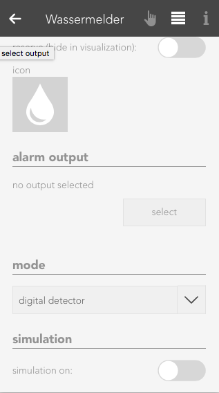
Icon
Defines which image should be used for this Detector.
Alarm Output
You can choose a digital output, which will be triggered in case of an alarm, here.
Mode
Here, the Digital Input which is used for this Detector can be switched back to another mode.
Simulation on
Activates the simulation and allows you to set a value via the setting 'Simulation Value'. Attention: If the simulation is active, real values are ignored!
Simulation Value
Change the simulated value with this setting.
Operation

After you changed a Digital Input into a Detector, it will react to incoming signals and trigger an alarm, depending on its configuration.
A detector will display if his input is currently active and if it is triggering an alarm.
Szenen
Der Melder bietet folgende Auslöser für evonHOME Szenen (Wenn...):
- Alarm wurde ausgelöst: Der Alarm des Melders wurde ausgelöst
- Alarm wurde beendet: Der Alarm des Melders wurde beendet
Counter
This app is used when you connect a counter to a digital input. With it's help you can react to the signals send form the counter unit and evaluate them. For example, you can record a power consumption in kW, set various value limits and react to them later in scenes.
The Counter ist located under “all apps” – “Counter”.
The minimum pulse length for a counter connected to a digital module is 100ms. For faster counters, please use the input located on the cpu module.
Create
To use a counter in combination with the corresponding app, you will have to connect it to a digital input of your evonHOME (DI1 - DI4 on the CPU or 'evonHOME Digital 1180' or 'evonHOME Digital 1344'). Then follow these steps:
If you find not create a counter in your evonHOME system yet, you have to convert a digital input into one.
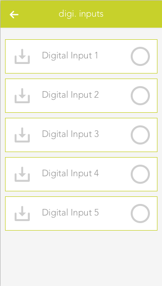
Navigate to te digital inputs in 'All Apps' - 'Digital Inputs', select the desired input and open the ParameterPanel.
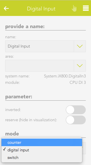
In the settings for mode, choose 'Counter'. The digital input will now be converted into a Counter an will be listed in the Counter app.
Configuration
Every Counter allow you to change certain settings, which determine what will be counted (e.g. kWh) and what limits exists.
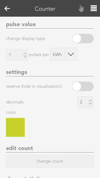
Pulse value
Choose the significance of the impulse which gets received by the counter. The necessary settings for this are usually listed on the counter device.
Settings
Inverted
If this option is activated, only falling edges will be counted instead of rising edges.
Reserve
Hides this counter from the visualization.
Color
Changes the color of the visible graphs.
Edit count
Here, you can set the current count to a desired value

Show statistics
Choose the graph/chart, which will be displayed in the OperatorPanel.
Limits
You can choose various limits (and according delays) here, which you can then link in scenes. Linkable values are: 'current consumption - upper limit', 'current consumption - lower limit' and 'daily consumption - limit'.
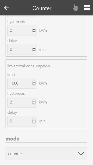
Mode
With this setting you can convert/revert a counter to a digital input or switch
Operation
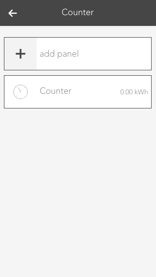
Once a Counter has been created, you can add additional visual panels. Those grant you an overview about the evaluated values.
To add such a panel, use the button "add panel".
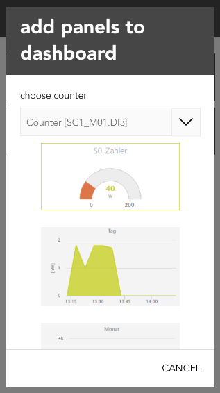
In the popup which will appear, you can choose between several graphs/charts. To do so, you have to select the corresponding Counter under 'choose counter' and then one of the desired charts.
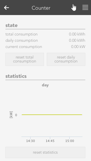
The OperatorPanel gives you an overview about the measured values. The following sections exist:
Status
Gives you information about the total, daily and current consumption. In addition, you can also reset the counter.
Statistic
The graphs/charts which you can activate in the ParamterPanel will be shown here. The statistics which are shown here can also be reset with the corresponding button.
Szenen
Der Zähler bietet folgende Auslöser für evonHOME Szenen (Wenn...):
- Grenzwert Gesamtverbrauch überschritten: Der Grenzwerte für den Gesamtverbrauch wurde überschritten
- Grenzwert Tagesverbrauch überschritten: Der Grenzwert für den Tagesverbrauch wurde überschritten
- Oberer Grenzwert aktueller Verbrauch überschritten: Der obere Grenzwert für den aktuellen Verbrauch wurde überschritten
- Unterer Grenzwert aktueller Verbrauch unterschritten: Der untere Grenzwert für den aktuellen Verbrauch wurde unterschritten
Der Zähler bietet folgende Funktionen für evonHOME Szenen (Dann...):
- Gesamtverbrauch zurücksetzen: Der Gesamtverbrauchszähler wird zurückgesetzt
- Tagesverbrauch zurücksetzen: Der Tagesverbrauch wird zurückgesetzt
REST API

Starting with version 1.4, your evonHOME offers you a REST API Service at "http://[evonHOME_IP]/api". The following steps are required to use it.
Preparation
- Navigate to 'Alle Apps' - 'Settings' - 'Rest Service' in the user interface of your evonHOME system.
- Enter your evonHOME credentials and generate a hash (You should save the hash value as it is needed for the following step).
Authentication
To send requests to the REST API, you must authenticate yourself. A token is used for this purpose, which you will receive once you make a successful login attempt via the REST API.
- Send a POST request to the following address:
"http://[evonHOME_IP]/login", with this header parameters:- x-elocs-username: [Username]
- x-elocs-password: [Hash]
You will receive a token 'x-elocs-token' as a response, which will automatically be set as a cookie. This token will now be used as an authentification for all further requests.
Depending on from where you are sending your requests, the cookie will automatically be used. Otherwise, you will have to add the token to the header of every request 'Cookie:token=[Token]'.
Requests
The evonHOME REST API allows you check the status of the components in your system and to control them. The following requests are available to you:
GET: apps
"http://[evonHOME_IP]/api/apps"
Returns a list of all apps.
GET: apps/{fullName}
Returns detailed information about the requested app.
GET: instances
Returns a list of all instances.
GET: instances/{instanceId}
Returns detailed informations about the requested instance.
GET: instances/{instanceId}/{action}
Returns the current value of the requested property of a specific instance. For example, the current state of a light.
POST: instances/{instanceId}/{action}
Calls a method of the specific instance.
You can find a test interface at "http://[evonHOME_IP]/api", which allows you to try out all listed requests.
Examples
In the following example, we want to switch a light by using the REST API.
Before we can start, we have to make sure that the preparations for authentification are done (see topic "Preparation" and "Authentification"). With the received token, we are now able to send all requests and commands.
At first we send a GET request to `"http://[evonHOME_IP]/api/instances" and receive a list with all instances, which are currently active in the evonHOME system.
"statusCode": 200,
"statusText": "success",
"data": [
{
"ID": "SC1_M04.Light1",
"ClassName": "SmartCOM.Light.Light",
"Name": "Roomlight",
Group": "AreaOutdoor
},
...
]
}```

As we want to switch a light, we choose the 'Roomlight' and use its "ClassName": "SmartCOM.Light.Light" to send a GET request to `"http://[evonHOME_IP]/api/apps/SmartCOM.Light.Light"` and receive the available methods and properties.

```{
"statusCode": 200,
"statusText": "success",
"data": {
"methods": [
{
"parameter": [],
"name": "SwitchOn",
"type": 0,
"derived": false,
"tags": [
linkable
],
"returnType": "void",
"description": "switch light on",
"isStatic": false
},
...
],
"properties": [
{
"name": "IsOn",
"type": "boolean",
"remark": "light switched on",
"declaration": "2",
"derived": true,
"parameter": false,
"tags": [
linkable
],
"isStatic": false
},
...
],
"fullName": "SmartCOM.Light.Light",
"displayName": "Light",
"autoStart": false
}
}```

We are now sending a POST request to `"http://[evonHOME_IP]/api/instances/SC1_M04.Light1/SwitchOn"` with the following parameters in the header:
- instanceId: SC1_M04.Light1
- action: SwitchOn
- body: [ ]

This will call the specified method of the light and switch it on. We can also check the current status by sending a GET request to `"http://[evonHOME_IP]/api/instances/SC1_M04.Light1/IsOn"` and receive a response containing the current status, in this case 'true'.

```{
"statusCode": 200,
"statusText": "success",
"data": true
}```
uLux
The app allows you to configure the evonHOME uLux switch.

The uLux app is located under “all apps” – “uLux”.
Important: To integrate the uLux switch into evonHome, the required uLux design-template must be present on it. In delivery state, all evonHOME uLux switches already contain this template. Further configuration with the uLux software is not required.
Create
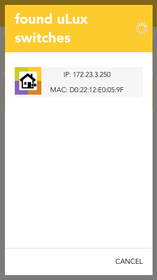
To create a new uLux room, click on the add symbol, after which a search for uLux switches in your network is started. If the switch is not immediately found, you can just restart the search. Once the uLux is found, you just have to select it to add it to your system.
Configuration
After the uLux switch has been found, you only need to add a name, a room and an IP-address.
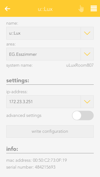
Settings
Here, you can change the network address of your uLux switch.
If you edit this settings, you will have to press the button 'write configuration' to transfer them to your uLux switch. The switch will then restart and boot up with your new configuration after some seconds.
Operation
The uLux switch works like a room control. This makes it easy to add all elements from a room (lights, blinds, heating, scenes) to it.
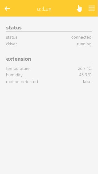
Just add a name and room to your uLux switch and once you finish the configuration every element from this room will automatically be displayed on the switch.
If an uLux extension module is connected, your can find all measured values in the 'extension' section. Those values can also be linked in the Logic app.
Szenen
Der u::LUX Schalter bietet folgende Auslöser für evonHOME Szenen (Wenn...):
- Bewegung erkannt (Erweiterungsmodul): Am u::LUX wurde eine Bewegung erkannt (Nur mit Erweiterungsmodul möglich)
Access Control
Erstellen

Nachdem der Fingerscanner an das passende "evonHOME Auxiliary – RS485" Modul angeschlossen wurde, kannst Du diesen im evonHOME System hinzufügen.
Lege dazu ein neues Zutrittssystem über den entsprechenden Button an.

Im nun erscheinenden Popup werden alle erkannten Zutrittssysteme gelistet. Du kannst das gewünschte System über einen Klick auf den Namen oder das Plus Symbol hinzufügen.
Wenn Du mehrere Zutrittssysteme besitzt, kannst Du den zweiten Button benutzen um die LEDs des verlinkten Systems aufblinken zu lassen und es dadurch identifizieren.

Wurde ein System ausgewählt, kannst Du diesem im zweiten Schritt einen Namen geben.

Hast Du Deine Eingabe bestätigt, wird das Zutrittssystem erstellt und Du kannst mit der Konfiguration beginnen.
Konfiguration

Klicke zur Konfiguration deines Fingerscanners einmal auf das neue erstellte Zutrittsystem und navigiere zu den Einstellungen in das ParameterPanel.

Im Bereich "Status" werden Dir Informationen über die Verbindung zu deinem Zutrittssystem angezeigt.
Wenn Du mehrere Zutrittssysteme besitzt, kannst Du den Button "Identifizieren" benutzen um die LEDs des verlinkten Systems aufblinken zu lassen und es dadurch zu finden.

Nun kannst Du damit beginnen Nutzer anzulegen, für die Du anschließend Finger oder RFID Chips einlernen kannst.
Klicke hierzu auf das Plus Symbol.

Du wirst nun durch die einzelnen Schritte geleitet, die für das Anlegen eines Benutzers und dem Einlernvorgang notwendig sind.
Wähle zuerst den evonHOME Benutzer aus für den Du Finger oder RFID Chips einlernen willst.

Als nächstes siehst du eine Übersicht der bereits eingelernten Finger/Chips. Klicke auf das Plus Symbol um weitere hinzuzufügen.

Wähle nun den gewünschten Finger oder RFID Chip aus und klicke auf "Einlernen".
Der Einlernvorgang wird nun gestartet und Dein Fingerscanner blinkt orange. Ziehe nun den betreffenden Finger mehrmals langsam über den Scanner, bis dieser blau leuchtet. Der Finger wurde nun erfolgreich eingelernt.
Du kannst nun weitere Finger oder einen RFID Chip einlernen. Sobald Du fertig bist klicke auf "weiter".

Wenn Du eine Tür mit Türöffner besitzt kannst du diese im nächsten Schritt mit Deinem ausgewählten Benutzer verknüpfen. Dadurch wird die Tür entsperrt, sobald der Finger oder RFID Chip des Benutzers erkannt wird.

Sobald Du auf "Weiter" klickst, ist die Konfiguration abgeschlossen und Du kannst Deine Änderungen über einen Klick auf "Fertig" bestätigen. Alternativ kannst Du auch ein paar Schritte zurück gehen und noch weitere Finger/RFID Chips hinzufügen.
Alle erstellten Benutzer erscheinen nun in der Liste des Zutrittsystems. Neben jedem befindet sich ein kleines Schloss, über das der betreffende Benutzer gesperrt werden kann, wodurch er keine Zutrittsberechtigung mehr hat.
Außerdem können Benutzer über das X-Symbol gelöscht oder bei Klick auf den Namen angepasst werden.
Der Schalter "Deaktiviert" ermöglicht das manuelle temporäre deaktivieren des Zutrittsystems im Falle eines Defekts etc. Ein konfiguriertes Zutrittsystem wird außerdem automatisch deaktiviert, wenn dieses für eine gewisse Dauer nicht erreichbar ist.

Falls Du später weitere Finger/RFID Chips zu einem bereits angelegten Benutzer hinzufügen möchtest, musst Du nur auf den betreffenden Namen in der Liste klicken.
In der sich öffnenden Ansicht siehst Du nun alle bisher eingelernten Finger/RFID Chips, kannst diese löschen oder (über das Tür-Symbol) für den Türöffner deaktivieren. Außerdem kannst Du verknüpfte Türen zu diesem Benutzer hinzufügen und entfernen.
Dein Zutrittssystem steht Dir auch bei der Erstellung von Szenen zur Verfügung. Da viele Funktionen jedoch an einen Nutzer gekoppelt sind, findest du alle Auslöser, die einen bestimmen Nutzer betreffen unter "Benutzer".
Beispiel:
Wenn Du eine Szene erstellen willst, die ausgelöst wird, sobald irgendein beliebiger Finger erkannt wird, findest Du die betreffenden Funktionen unter "Wenn"-"Apps"-"Zutrittssystem".
Möchtest Du eine Szene auslösen, wenn ein bestimmter Benutzer oder damit verknüpfter Finger erkannt wird, befinden sich diese Auslöser unter "Wenn"-"System"-"Benutzer".
Szenen
Das Zutrittssystem bietet folgende Auslöser für evonHOME Szenen (Wenn...):
- Finger/RFID erkannt: Ein eingelernter Finger, RFID-Token oder RFID-Karte wurde erkannte
- Finger/RFID nicht erkannt: Der benutze Finger bzw. die RFID -Karte wurden nicht erkannt
Musik
Wenn Du ein angeschlossenes Audiomodul besitzt, kannst Du es mit Hilfe der App "Musik" steuern. Jedes Audiomodul, bietet 4 einzelne Ausgänge an denen Du Lautsprecher anschließen kannst, welche dann über die "Musik" App konfiguriert werden können. Außerdem ermöglicht dir dieses Modul die Wiedergabe von Musik aus bis zu 4 verschiedenen Quellen.

Du findest die Anwendung unter 'Alle Apps' - 'Musik'.
Konfiguration
Sobald ein neues Audiomodul an Dein evonHOME System angeschlossen wurde, kannst Du bereits mit der Konfiguration deiner Lautsprecher und Quellen beginnen. Befolge dazu folgende Schritte:

Bevor Du die einzelnen Quellen und Lautsprecher an Deine Wünsche anpassen kannst, solltest Du zuerst ein paar grundlegende Einstellungen für dein Audiomodul vornehmen.
Navigiere dazu nach 'Alle Apps' - 'Hardware', wo Dein neues Audiomodul gelistet wird.

Öffne nun die zugehörigen Einstellungen durch einen Klick auf den Namen des Moduls.
Hier solltest Du zu allererst festlegen, wie Du Deine Lautsprecher verwenden willst. Du hast die Auswahl zwischen Mono oder Stereogruppen, kannst aber auch alle 4 Lautsprecherausgänge als gemeinsame Gruppe zusammenfassen.
Je nachdem, welche Auswahl Du hier triffst, erscheinen betreffende Lautsprecher in der Musik-App.

Einige Lautsprecher sollten nur mit einer gewissen maximalen Lautstärke betrieben werden um diese nicht zu beschädigen. Daher hast Du hier die Möglichkeit sowohl die maximale als auch die minimale Lautstärke für alle angeschlossenen Lautsprecher einzustellen.
Darüber hinaus kann das Audiomodul neu initialisiert werden.
Bedienung

Hast Du alle Einstellungen durchgeführt kannst Du bereits zu 'Alle Apps' - 'Musik' navigieren, wo Du nun alle verfügbaren Quellen sowie Lautsprecher wiederfindest.
Quellen

Jedes Audiomodul verfügt über vier verschiedene Quellen, welche Deinen Lautsprechern zugewiesen werden können. Während "FM-Radio" und "Aux" fest vorgegeben sind, kannst Du für die übrigen zwei zwischen mehreren Optionen wählen.
Zur Auswahl stehen:
- "Lokale Dateien"
- "Internet Radio"
- "Airplay"
- "Medienserver(UPnP)"
Du solltest hier eine Auswahl treffen, damit Du diese Quellen verwenden kannst.
Je nach gewählter Option stehen dir verschiedene Möglichkeiten zur Bedienung zur Verfügung. So kannst du bei "Internet Radio", "Medienserver" sowie bei den "Lokale Dateien" durch die Liste an verfügbaren Medien/Sendern navigieren und Favoriten setzen. Im Falle von Airplay lässt sich der Name ändern, der bei einer Suche auf deinem Endgerät angezeigt wird.

In den Einstellungen jeder Quelle hast Du außerdem die Möglichkeit einen oder mehrere Lautsprecher für die Ausgabe zuzuweisen sowie die aktuelle Ausgabe zu überprüfen und mittels entsprechender Buttons zu steuern.

Zur zusätzlichen Anpassung der Audiowiedergabe, steht dir im Parameterpanel der anpassbaren Quellen noch ein Equalizer zur Verfügung
FM-Radio

Der FM-Radio ermöglicht zusätzlich zu den 2 dynamisch verwendbaren Quellen die Musikausgabe auf den Lautsprechern. In der Fußzeile können beliebige UKW-Radiosender gespeichert werden. Die Vor/Zurück-Icons ermöglichen das manuelle Einstellen der Frequenz bzw. einen automatischen Sendersuchlauf. Das Anzeigefeld der aktuellen Frequenz kann auch zur direkten Frequenz-Vorgabe verwendet werden.
Für den optimalen Empfang wird die Verwendung einer externen Wurfantenne empfohlen.
Lautsprecher

Je nachdem, welche Einstellungen (Stereo und Mono Gruppen) Du bei der Konfiguration deines Audiomoduls vorgenommen hast , werden Dir zwischen 1 und 4 Lautsprecher angezeigt.

Im ObjectPanel deines Lautsprechers werden die Informationen über die aktuelle Medienwiedergabe angezeigt. Darüber hinaus kannst du hier auch die Lautstärke verändern, wenn du die passende Panelgröße eingestellt hast.

Du kannst jedem Lautsprecher eine von den verfügbaren 4 Quellen zuweisen. Wurde eine Quelle ausgewählt, siehst du im unterem Bereich der Anzeige was gerade gespielt wird und kannst die Lautstärke anpassen.
Bei der Verwendung von Airplay als Quelle kann die Lautstärke der Wiedergabe zusätzlich über das verbundene Gerät gesteuert werden.
Es empfiehlt sich daher die Lautstärke des Lautsprechers etwas höher zu stellen oder anzupassen.

In den Einstellungen des Lautsprechers kannst Du wie gewohnt den Namen und den zugewiesenen Raum anpassen. Außerdem siehst du Informationen über den einzelnen Lautsprecher.

Darüber hinaus kannst Du Deinem Lautsprecher einen Taster zuweisen, über den die Wiedergabe gesteuert werden kann.
Die Geschwindigkeit, mit der die Lautstärke bei einem langen Tastendruck verändert wird, kann mit einem Schieberegler angepasst werden.
Möchtest Du, dass die Wiedergabe nach einer festgelegten Zeitspanne automatisch stoppt, kannst Du den "Sleep Timer" aktivieren und nach Deinen Wünschen anpassen.
Szenen
Die Musik App bietet folgende Funktionen für evonHOME Szenen (Dann...):
- Internet Radio abspielen: Die Quelle wird mit dem Internet -Radio belegt
- Lokale Dateien - Favoriten abspielen: Ein beliebiger Favorit der lokalen Dateien wird auf der Quelle abgespielt
- Medienserver - Favoriten abspielen: Ein beliebiger Favorit vom Medienserver(NAS) wird auf der Quelle abgespielt
- Nächster Titel/Stream: Auf den nächsten Titel/Stream wird gewechselt
- Voriger Titel/Stream: Auf den vorherigen Titel/Stream wird gewechselt
- (UKW) Frequenz einstellen: Eine beliebige Frequenz kann für den UKW-Radio vorgegeben werden
- (UKW) Sender suchen: Der Sendersuchlauf für den UKW-Radio wird gestartet
Modbus
Erstellen
Bevor die Kommunikation zwischen evonHOME und Deinem Modbus Gerät hergestellt werden kann, muss dieses zuerst in dein Netzwerk integriert werden. Lies dazu am besten die Anleitung des betreffenden Geräts, welche auch Informationen über die möglichen schreib-/lesbaren Werte enthalten sollte sowie über betreffende Modbus Register.

Hast Du dein Modbus Gerät erfolgreich in Betrieb genommen, kannst Du damit beginnen, es in Dein evonHOME System zu integrieren.
Wähle hierzu "Neues Gerät hinzufügen".

Dadurch wird ein neues Modbus Gerät im System angelegt und kann konfiguriert werden.
Konfiguration

In den Einstellungen des neu erstellten Modbus Gerätes solltest Du als erstes einen Namen und einen Raum vergeben.
Anschließend musst Du die Netzwerk Adresse (IP, Port) sowie SlaveID des Modbus Geräts eingeben.
Wurde die Verbindung erfolgreich hergestellt, ändert sich der angezeigte Status von "Nicht Verbunden" auf "Verbunden".

Als Nächstes benötigst Du die gerätespezifischen Informationen über les-/schreibbare Register, auf die Du mit der evonHOME Modbus Schnittstelle zugreifen kannst.
Diese musst du den Unterlagen deines Modbus Gerätes entnehmen.
Hast Du alle benötigten Informationen gesammelt, ist es an der Zeit, die passenden Register anzulegen. Navigiere zu dem Bereich "Register editieren" und wähle "Editieren".

Du befindest dich nun in der Registeransicht, in der Du neue Register hinzufügen oder anpassen kannst.
Es stehen Dir hier 4 verschiedene Registerarten zu Verfügung:
Coil Status (1 Bit, Lesen-Schreiben: FC=01)
Einzelner Ein-/Ausgang.
Holding Register (16-Bit, Lesen-Schreiben: FC=03)
Analoger Ein-/Ausgang.
Input Register (16-Bit, Nur Lesen: FC=04)
Analoger Eingang.
Input Status (1 Bit, Nur Lesen: FC=02)
Einzelner Eingang.
Welche Register für Dein Modbus Gerät verwendbar sind, sowie deren Konfigurationsdaten (Adresse, Datentyp, Lese-/Schreibzugriff) musst Du den Informationen entnehmen, die Deinem Gerät beiliegen.
In den Einstellungen jedes angelegten Registers müssen diese anschließend eingetragen werden.
Neben den spezifischen Konfigurationsmöglichkeiten für jedes Register, kann auch festgelegt werden, ob der Zugriff "Lesend" oder "Schreibend" erfolgt. Bei Schreibzugriff erscheinen in der Bedienoberfläche des Registers sowie des angelegten Modbus Gerätes in evonHOME zusätzliche Bedienelemente über die die geschriebenen Werte verändert werden können.
In den Einstellungen des im evonHOME System angelegten Modbus Gerätes kannst du die Konfiguration deiner Register exportieren und damit sichern, um sie später wieder importieren zu können (auch in ein anderes evonHOME System).
Zusätzlich lässt sich einer der Register als Anzeigewert auswählen, welcher im ObjectPanel deines Modbus Gerätes sichtbar ist und Farbe sowie Icon ändern.
Bedienung

Die Statuswerte und Bedienelemente aller angelegten Register erscheinen im OperatorPanel des Modbus Gerätes. Nach der Konfiguration kann das Gerät hier gesteuert und ausgelesene Werte kontrolliert werden.
Neben der Bedienung über diese Ansicht, kann auch innerhalb der evonHOME Logik App auf alle Register zugegriffen werden.
Dadurch lassen sich komplexe Abläufe umsetzen.
Intercom
Erstellen
Um die Türsprechanlage im evonHOME einbinden zu können, muss sich diese im selben Netzwerk wie Dein evonHOME System befinden.

Sobald Deine Türsprechanlage montiert und an Dein Netzwerk angeschlossen wurde, kannst Du diese in dein evonHOME System einbinden.
Lege dazu eine neue Sprechanlage über den entsprechenden Button an. Im nun erscheinenden Popup wird automatisch nach der Türsprechanlage gesucht. Sobald sie gelistet wird kannst Du sie auswählen und hinzufügen.
Sollte Deine Türsprechanlage nicht automatisch gefunden werden, kannst du diese auch über den Button "Manuell" selbst anlegen. In diesem Fall musst Du die IP Adresse der Anlage kennen und sie in den Einstellungen eintragen.

Eine neue Sprechanlage ist nun angelegt and kann konfiguriert werden.
Konfiguration

Wurde Deine Sprechanlage automatisch im Netzwerk gefunden und hinzugefügt musst Du die IP Adresse in den Einstellungen nicht mehr angeben.
Deine Sprechanlage wird sofort nach dem Anlegen vom System konfiguriert und startet von selbst neu. Es kann 1-2 Minuten dauern, bis der Vorgang abgeschlossen wurde und die Sprechanlage wieder verbunden ist.

Wurde die Sprechanlage manuell von Dir angelegt, musst Du in die Einstellungen gehen und die IP Adresse eintragen. Nutzername und Passwort sind bereits ausgefüllt, können aber jederzeit geändert werden, falls Du diese in der Türsprechanlage angepasst hast.

Wenn die Sprechanlage manuell hinzugefügt wurde, wird sie nach dem Eintragen nicht automatisch konfiguriert und startet daher nicht von selbst neu. Dadurch kannst Du auch bereits konfigurierte Sprechanlagen in das System einfügen, ohne das die Einstellungen erneut übertragen werden müssen.
Wenn Du eine neue Sprechanlage manuell hinzufügst, musst Du daher nach dem Eintragen der IP Adresse in den Abschnitt "Erweiterte Parameter" navigieren und den Punkt "Sprechanlage Konfiguration zurücksetzen". Nach dem anschliessenden Neustart der Türsprechanlage ist diese betriebsbereit.
Es ist wichtig, dass die Konfiguration der Sprechanlage durchgeführt wird, da erweiterte Funktionen wie die Erkennung der Klingel- und Licht-Tasten sonst nicht funktionieren.
If you want to be able to use the built in microphone and speaker of your intercom to talk to visitors, we recommended to download and use the following apps:
iOS - https://itunes.apple.com/at/app/mobotix/id527836206?mt=8
Android - https://play.google.com/store/apps/details?id=org.abionix.axviewer&hl=de
Bedienung

Wurde die Verbindung mit der Sprechanlage erfolgreich hergestellt siehst Du im OperatorPanel das aktuelle Videobild.
Über das Pfeilsymbol auf dem Bild kannst Du dir auch eine vergrößerte Version der Übertragung ansehen.
Falls die Sprechanlage manuell hinzugefügt wurde und Du noch die IP Adresse eintragen musst, erscheinen hier statt der Videoübertragung die betreffenden Eingabefelder.
Da die Türsprechanlage auch über eine Klingeltaste verfügt, kannst Du sie mit einer Tür verknüpfen. Navigiere dazu in die Tür App und wähle eine passende Tür aus. In den Einstellungen kannst Du nun die Sprechanlage hinzufügen. Wird die Klingeltaste betätigt, erhältst Du eine Benachrichtigung mit dem aktuellen Videobild. Außerdem wird eine Aufnahme des Kamerabilds gespeichert. Wenn Du einen Türöffner besitzt, kannst Du diesen in dem im evonHome System erscheinenden Popup bedienen.
Du kannst die Klingel und Lichttaste der Sprechanlage auch als Auslöser für das Erstellen von Szenen in der betreffenden App verwenden.

Das ObjectPanel der Sprechanlage kann auch über das Menü, das erscheint, wenn Du mit Deinem Finger bzw. der Maustaste länger auf dem Element bleibst/gedrückt hältst, vergrößert werden. Dadurch wird hier ebenfalls das Kamerabild eingeblendet.
Du kannst die Sprechanlage auch auf deinen Startbildschirm legen um so das Kamerabild immer sichtbar zu haben.
Szenen
Die Sprechanlage bietet folgende Auslöser für evonHOME Szenen (Wenn...):
- Klingeltaste wurde gedrückt: Die Klingeltaste an der Außenstelle wurde betätigt
- Lichttaste gedrückt: Die Lichttaste an der Außenstelle wurde betätigt
- Tastenfeld Zugang gewährt: Der korrekte Code wurde an der Tastenfeld -Erweiterung eingegeben
- Tastenfeld Zugang verweigert: Ein falscher Code wurde an der Tastenfeld -Erweiterung eingegeben
- Türöffner aktiviert: Über das Mobotix Interface oder App wurde der Türöffner aktiviert
Fehlersuche
Sollte es zu Problemen bei der Erkennung der Klingel- oder Lichttaste der Sprechanlage kommen, kannst Du folgende Punkte überprüfen.
Damit das Betätigen der Sprechanlage Tasten in evonHOME erkannt wird, muss diese zuerst in evonHOME eingebunden werden. Die notwendige Konfiguration geschieht automatisch im Hintergrund, sobald Du die vom System gefundene Sprechanlage hinzufügst. Sollt es sich um eine Sprechanlage handeln, die mit einem Tastenfeld verwendet wird, musst Du im SettingsPanel unter "Erweiterte Parameter" den Punkt "Sprechanlage mit Tastenfeld Konfiguration zurücksetzen" wählen. Das kannst Du entweder bei einer bestehenden Sprechanlage durchführen oder wenn Du sie manuell hinzufügst.
Weitere Einstellungen sind für die Erkennung der beiden Tasten der Sprechanlage nicht notwendig. Sollte die IP Adresse der evonHOME Engine später geändert werden, muss die Sprechanlage über das SettingsPanel wieder zurückgesetzt werden.
Überprüfung Konfiguration
Im Settingspanel der Kamera kann unter "Erweiterte Parameter" sowohl die Klingel- als auch Lichttaste geprüft werden. Ist die Konfiguration der Mobotix Sprechanlage korrekt, werden zugehörige Events ausgelöst bzw. die Anzeigen auf dem ObjectPanel aktiviert.
Sollte dies fehlschlagen, können folgende Einstellungen im Webinterface der Sprechanlage überprüft werden:

1 - Navigation in das Admin Menü zu "Profile für Netzwerkmeldungen".

2 - Hier müssen sich Einträge für "Doorbell" sowie "LightSwitch" befinden. Jeder Eintrag enthält eine Zieladresse die mit der IP Adresse der evonHOME Engine übereinstimmen muss, sowie den vorgegeben Port "4500". Im Bereich "Datenprotokoll" befindet sich außerdem ein Eintrag für den "CGI"-Pfad, der den Systemnamen der Sprechanlage in evonHOME enthält. Dieser kann im SettingsPanel kontrolliert werden und muss mit dem hier eingetragenen Systemnamen übereinstimmen.


3 - Navigation in das Setup Menü zu "Ereignisübersicht"

4 - Im Bereich "Signalereignisse" muss es je einen Eintrag für die Klingel- sowie Lichttaste geben. Hier ist darauf zu achten, das diese nicht auf "Inaktiv" gesetzt sind.

5 - Navigation in das Setup Menü zu "Aktionsgruppen-Übersicht".

6 - Hier muss es ebenfalls Einträge für die Klingel- sowie Lichttaste geben. Unter "Bearbeiten" finden sich im Bereich "Ereignisauswahl" alle möglichen Signale, die als Auslöser dienen. Hier muss "CameraBellButton" für die Klingel- bzw. "CameraLightButton" für die Lichttaste ausgewählt sein (Passend zu den Signalen aus Punkt 4). Unter "Aktionen" muss die zugehörige Netzwerkmeldung aus Punkt 2 erscheinen.
Tastenfeld
Die Türsprechanlage kann mit einem Tastenfeld ergänzt werden, welches den Zutritt sowohl mittels Zugangscode als auch durch RFID Karten ermöglicht.
Einführung
Im Folgenden werden die notwendigen Schritte beschrieben, um eine Mobotix Türsprechanlage (T25) durch ein Tastenfeld zu erweitern und dieses soweit vorzubereiten, dass eine Einbindung in evonHOME möglich ist.
Die Notwendigen Schritte gliedern sich dabei in folgende Punkte:
- Anschluss und Verkabelung
- Reset der Mobotix (T25) Anlage
- Erstkonfiguration des Tastenfelds
- Einrichtung in evonHOME
https://cdn.competec.ch/documents/2/9/293364/Schnellinstallation_T25_DE.pdf
Reset der Mobotix (T25) Anlage
- Strom an -> Mobotix Kamera Tasten leuchten -> Klingeltaste gedrückt halten bis beide Tasten kurz blinken
- Kamera bootet neu und sagt IP Adresse an -> IP Adresse aufschreiben, da sie für die spätere Konfiguration benötigt wird.
Erstkonfiguration des Tastenfelds
Nach Abschluss des Resets der Mobotix Türsprechanlage (Durchsage der aktuellen IP Adresse):
- Keypad blinkt weiß, ESC-Taste blinkt rot und OK-Taste blinkt blau
- Gewünschten Super-PIN (8-16 Stellen) eingeben und mit OK bestätigen.
- Super-PIN erneut eingeben und nochmals mit OK bestätigen.
- Nach erfolgreicher zweimaliger Eingabe des Super-PIN leuchtet des Keypad kreisförmig weiß und das Keypad wechselt in den RFID Einlernmodus
- Im Lieferumfang des Keypads befinden sich mehrere RFID Karten: 1 Admin-Karte (rot) sowie mehrere User-Karten (blau).
- Die Admin-Karte (rot) nun ca 5 Sekunden vor das Tastenfeld halten, bis kein Signalton, mehr ertönt. Wurde die Admin-Karte korrekt eingelernt, leuchtet das Tastenfeld zur Bestätigung kurzfristig in Form eines Kreises (Tasten 2, 4, 6, 7, 9 ,0).
- Danach leuchten alle Tasten weiß, die ESC-Taste blau sowie die OK-Taste blau. Es können nun User-Karten eingelernt werden. Hierzu eine User-Karte vor das Tastenfeld halten und warten, bis die Bestätigung in Form des Kreises erscheint. Schritt für gewünschte Anzahl an eingelernten User-Karten wiederholen.
- Die Einlernzeit für User-karten endet nach 2 Minuten. Alternativ kann der Vorgang manuell beendet werden, indem die ESC-Taste gedrückt wird.
Achtung: Der eingegebene Super-PIN überschreibt das Factory Passwort der Türsprechanlage ("meinsm"). Für Zugriffe auf das Interface der Mobotix muss daher nach Einrichtung des Tastenfelds der Super-PIN als Passwort für den Login verwendet werden.
Zugangscodes einrichten
https://www.youtube.com/watch?v=BqQbM3qUbZM
Nach Abschluss der Erstkonfiguration können die eingelernten RFID Karten für den Zutritt verwendet werden. Um den einzelnen Karten Zugangscodes (4-16 Ziffern; Nur 0 nicht erlaubt) zuzuweisen, müssen folgende Schritte befolgt werden:
- OK-Taste gedrückt halten bis das Tastenfeld zwei Bestätigungstöne von sich gibt. -> OK-Taste blinkt nun blau
- Admin-Karte vor das Tastenfeld halten bis ein doppelter Bestätigungston erklingt. -> Ok-Taste leuchtet konstant blau
- Schlüssel-Taste drücken. -> Schlüsseltaste leuchtet konstant blau
- Ok-Taste gedrückt halten bis der zweite Bestätigungston erklingt. -> Schlüssel-Taste und OK-Taste leuchten konstant blau
- Nun muss die Nummer der Karte ausgewählt werden, für die ein Zugangscode eingerichtet werden soll. Dabei bestimmt die Reihenfolge, in der die Karten eingelernt wurden ihre Nummer. "1" ist somit die erste eingelernte Karte usw.
- Wähle nun die gewünschte Karte durch Eingabe der passenden Zahl und bestätige mittels Ok-Taste.
- Gib nun den gewünschten Zugangscode ein und bestätige mit der Schlüssel-Taste
- Wiederhole die Eingbabe und bestätige erneut mit der Schlüssel-Taste
- Das Tastenfeld bestätigt die Eingabe mit einem Bestätigungston und einem ringförmigen Leuchten der Tasten.
Einrichtung in evonHOME
Um die Mobotix Türsprechanlage mit dem Mobotix Keypad mit evonHOME zu verbinden, muss eine neue Sprechanlage hinzugefügt werden. Da die Zugangsdaten der Türsprechanlage durch die Installation des Tastenfeldes nicht mehr mit dem Auslieferungszustand übereinstimmen, muss dies über den manuellen Modus geschehen.
- Navigation zu "Alle Apps" Sprechanlage
- "Sprechanlage hinzufügen"
- Die Sprechanlage sollte automatisch mit der passenden IP-Adresse gefunden werden. Diese für den nächsten Schritt notieren (Es sollte sich um die selbe Adresse handeln, die beim Reset der Mobotix Sprechanlage durchgesagt wird).
- "Manuell" wählen.
- Die notierte IP-Adresse eingeben. Nutzername ist "admin", Passwort entspricht der am Mobotix Keypad eingerichteten Super-PIN.
- Sind die Daten korrekt, sollte das Bild der Sprechanlage angezeigt werden.
- Ins ParameterPanel navigieren -> "Erweiterte Parameter" öffnen und "Sprechanlage mit Tastenfeld Konfiguration zurücksetzen" wählen.
Heatpump
Erstellen
Die Anbindung und Steuerung einer Wärmepumpe an Dein evonHOME System erfolgt über digitale Eingänge und digitale oder analoge Ausgänge, je nachdem, was Deine Wärmepumpe unterstützt.

Wurde die Wärmepumpe an betreffende Ein- Ausgänge angeschlossen, muss sie in Deinem evonHOME System angelegt werden.
Wähle dazu "Wärmepumpe hinzufügen".

Nun wird eine neue Wärmepumpe erstellt und kann konfiguriert werden.
Konfiguration

Nachdem Du eine neue Wärmepumpe in evonHOME angelegt hast, solltest Du dieser zunächst einen Namen geben und sie einem Raum zuordnen.
In den Einstellungen hast Du auch die Möglichkeit, die Funktion "Betriebsmodus für Raumklima übernehmen" zu aktivieren. Ist diese Funktion aktiv, wird bei Änderung des Betriebsmodus (Heizen/Kühlen) der Wärmepumpe auch der Modus des Raumklimas in den Einstellungen angepasst.

Um die angebundene Wärmepumpe zu steuern oder ihren aktuellen Status zu erhalten, musst Du die passenden Ein- und Ausgänge auswählen, über die sie an Dein evonHOME System angeschlossen wurde.
Über die digitalen Eingänge hast Du die Möglichkeit, den Status folgender Werte zu erhalten:
Ein/Aus
Stellt den aktuellen Betriebszustand dar.
Modus (Heizen/Kühlen)
Der Aktuelle Betriebsmodus der Wärmepumpe.
Störung
Wird verwendet um eine Störung der Pumpe zu melden.
Da nicht jede Wärmepumpe die digitalen Signale gleich handhabt, kannst Du für jeden Eingang einstellen, wie diese interpretiert werden.
Die Verwendung der digitalen Eingänge ist für den Betrieb der Wärmepumpen-App nicht zwingend erforderlich. Solltest Du nicht alle oder keine der digitalen Eingänge konfiguriert haben, werden für die angezeigten Werte (Modus, Status) die aktuellen Zustände der digitalen Ausgänge verwendet.

Über die digitalen Ausgänge hast Du die Möglichkeit, den Status folgender Werte zu ändern:
Ein/Aus
Stellt den aktuellen Betriebszustand dar. Dieser Ausgang ist zwingend erforderlich um die Wärmepumpe in Betrieb zu nehmen und die anderen Bedienelemente zu aktivieren.
Modus (Heizen/Kühlen)
Der Aktuelle Betriebsmodus der Wärmepumpe.
Auch hier kann eingestellt werden, wie die Signale interpretiert werden.
Steuerung der Betriebsstufe
Für die Steuerung der Betriebsstufe kannst Du zwischen analogem oder digitalem Ausgang wählen. Bei analoger Steuerung benötigst Du nur einen einzelnen Ausgang über den sich die Betriebsstufe in 10 Stufen regeln lässt.
Bei der Verwendung von digitalen Ausgängen werden 3 einzelne digitale Ausgänge benötigt, über die die Wärmepumpe in 3 Stufen geregelt werden kann.
Operation
Szenen
Die Wärmepumpe bietet folgende Auslöser für evonHOME Szenen (Wenn...):
- Betrieb Aus: Die Wärmepumpe wurde ausgeschaltet
- Betrieb Ein: Die Wärmepumpe wurde eingeschaltet
- Modus Heizen: Der Modus der Wärmepumpe wurde auf Heizen gestellt
- Modus Kühlen: Der Modus der Wärmepumpe wurde auf Kühlen gestellt
- Störung erkannt: Eine Störung der Wärmepumpe wurde gemeldet
Die Wärmepumpe bietet folgende Funktionen für evonHOME Szenen (Dann...):
- Ausschalten: Die Wärmepumpe wird ausgeschaltet
- Betriebsstufe setzen: Eine beliebige Betriebsstufe kann für das Gerät gesetzt werden
- Einschalten: Die Wärmepump wird eingeschaltet
- Heizen: Der Modus Heizen wird aktiviert
- Kühlen: Der Modus Kühlen wird aktiviert
Ventilation
Erstellen
Die Anbindung und Steuerung einer Lüftung an Dein evonHOME System erfolgt über digitale Eingänge und digitale oder analoge Ausgänge, je nachdem, was Deine Lüftung unterstützt.

Wurde die Lüftung an betreffende Ein- Ausgänge angeschlossen, muss sie in Deinem evonHOME System angelegt werden.
Wähle dazu "Lüftung hinzufügen".

Nun wird eine neue Lüftung erstellt und kann konfiguriert werden.
Konfiguration

Nachdem Du eine neue Lüftung in evonHOME angelegt hast, solltest Du dieser zunächst einen Namen geben und sie einem Raum zuordnen.
Um die angebundene Lüftung zu steuern oder ihren aktuellen Status zu erhalten, musst Du die passenden Ein- und Ausgänge auswählen, über die sie an Dein evonHOME System angeschlossen wurde.
Über die digitalen Eingänge hast Du die Möglichkeit, den Status folgender Werte zu erhalten:
Ein/Aus
Stellt den aktuellen Betriebszustand dar.
Störung
Wird verwendet um eine Störung der Lüftung zu melden.
Da nicht jede Lüftung die digitalen Signale gleich handhabt, kannst Du für jeden Eingang einstellen, wie diese interpretiert werden.
Die Verwendung der digitalen Eingänge ist für den Betrieb der Lüftungs-App nicht zwingend erforderlich. Solltest Du den Eingang für den Betriebsstatus nicht konfiguriert haben, wird für den angezeigten Wert der aktuelle Zustand des entsprechenden digitalen Ausgangs verwendet.

Über die digitalen Ausgänge hast Du die Möglichkeit, den Status folgender Werte zu ändern:
Ein/Aus
Stellt den aktuellen Betriebszustand dar. Dieser Ausgang ist zwingend erforderlich um die Lüftung in Betrieb zu nehmen und die anderen Bedienelemente zu aktivieren.
Es kann zusätzlich eingestellt werden, wie das Signal interpretiert werden soll.
Steuerung der Betriebsstufe
Für die Steuerung der Betriebsstufe werden 3 einzelne digitale Ausgänge benötigt, über die die Lüftung in 3 Stufen geregelt werden kann.
Operation
Szenen
Die Lüftung bietet folgende Auslöser für evonHOME Szenen (Wenn...):
- Wurde aktiviert: Die Lüftung wurde aktiviert
- Wurde deaktiviert: Die Lüftung wurde deaktiviert
- Störung erkannt: Eine Störung an der Lüftungsanlage wurde gemeldet
Die Lüftung bietet folgende Funktionen für evonHOME Szenen (Dann...):
- Ausschalten: Das Gerät wird ausgeschaltet
- Betriebsstufe setzen: Eine beliebige Betriebsstufe kann für das Gerät vorgegeben werden
- Einschalten: Das Gerät wird eingeschaltet
Sprachausgabe
Die Sprachausgabe gibt Dir die Möglichkeit, von Dir eingegebene Texte über die an Dein evonHOME Soundmodul angeschlossenen Lautsprecher wiederzugeben.

Du findest die Anwendung unter 'Alle Apps' - 'Sprachausgabe'.
Konfiguration

Bevor Du konfigurierte Texte über dein Soundmodul wiedergeben kannst, solltest Du zuerst bestimmen, welche Lautsprecher dafür verwendet werden sollen. Dies kannst Du in den Einstellungen der Sprachausgabe tun.
Hier hast Du außerdem die Möglichkeit einen Signalton zu aktivieren, der vor jeder Sprachausgabe abgespielt wird.
Bedienung

In der Bedienoberfläche der Sprachausgabe kannst Du den Text eingeben, der gesprochen werden soll. Außerdem ist es möglich, die Lautstärke der Ansage einzustellen.
Über den Button "Sprechen" wird die Wiedergabe auf den von Dir ausgewählten Lautsprechern gestartet. Darüber hinaus kannst du die Sprachausgabe auch in selbst erstellten Szenen verwenden, um Texte wiederzugeben.
Szenen
Die Sprachausgabe bietet folgende Funktionen für evonHOME Szenen (Dann...):
- Sprechen: Der eingegebene Text wird mit festgelegter Lautstärke gesprochen
Netatmo
The Netatmo App allows you to integrate your Netatmo Weatherstation and its Rain Gauge extension.

The Netatmo app is located under “all apps” – “Netatmo”.
Create
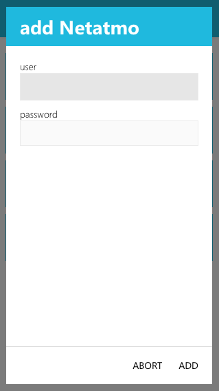
Once inside the Netatmo app, you can add your weather station with "add Netatmo". There, you will have to enter your Netatmo credentials to link your account with evonHOME.
Confirm to proceed.
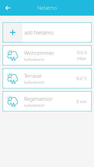
If your login was successful, the system will fetch all your Netatmo Weather Stations from your account and add them to your evonHOME.
Configuration
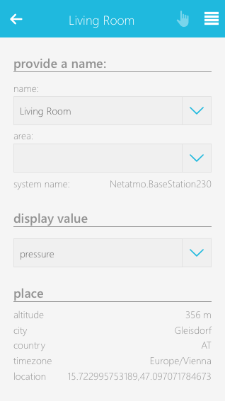
The ParameterPanel of each Netatmo Device allows you to adjust its name and area as well as its displayed value, which will be shown in the ObjectPanel of the Device. For example, the Netatmo Base Station lets you select one of the following values:
- noise
- temperature
- humidity
- pressure
- CO2
Besides choosing a display value, you will also find a list of basic location information for the current Netatmo device, which are fetched from your Netatmo account.
Operation
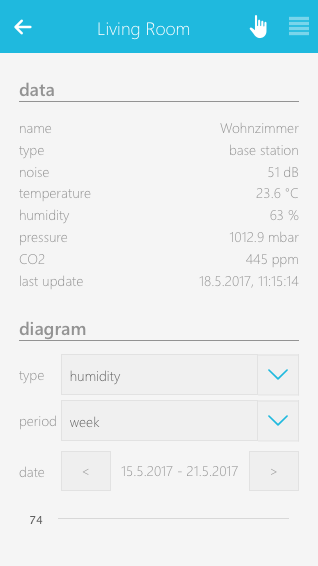
The OperatorPanel of your Netatmo Device will list its aggregated data like noice, temperature, pressure and more.
It will also display the last time those values were loaded from the device.
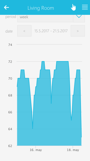
At the bottom of the panel, you will find a diagram displaying all records for a selected value over a chosen time. You can change the value or timeframe via the provided dropdowns.
Philips Hue
The Philips Hue App makes it possible to integrate Philips Hue lights into your evonHOME.

“Philips Hue” is located under “all apps” – “settings” - "Philips Hue".
Creation
Before you can use your Philip Hue lights inside evonHOME you will have to connect the Philips Hue Bridge to it. Make sure that the Bridge is on the same network as your evonHOME system and follow these steps.

Navigate to "All Apps" - "Settings" - "Philips Hue".
All Philips Hue Bridges which are connected to evonHome will be listed here. To add a new bridge to your system, use the "add new bridge" panel.
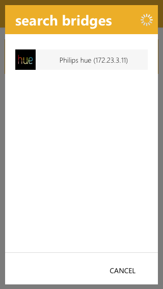
evonHOME will now start to search for all available Philips Hue Bridges inside your local network and lists them inside a popup.

Select the Philips Hue Bridge you want to add to evonHOME. You will be asked to press the link button on your Philips Hue Bridge to confirm the connection.
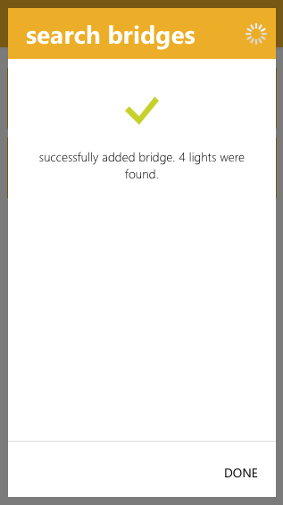
If the connection was established, you will be presented with a success message. You can close the popup now.
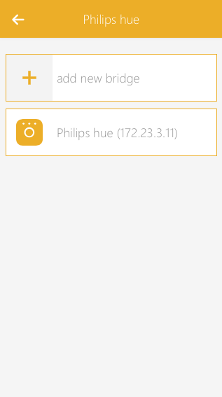
Your Philips Hue Bridge is now connected to your evonHOME system.
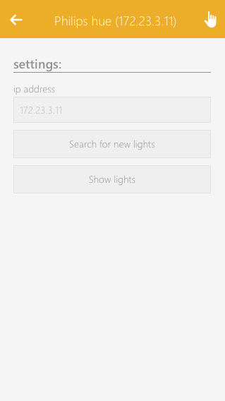
All Philips Hue lights, which are linked with the bridge, will also be added to your evonHOME system. In case you are changing your Philips Hue configuration in the future (adding or removing Philips Hue lights) you can use the "Search for new lights" button in the OperatorPanel.
Use the "Show lights" button to go to the list of all currently connected Philips Hue lights.
Notice that all connected Philips HUE lights will also be listed in the Lights App, which you can find under "All apps" - "Lights".
Configuration
Besides adding the Philips Hue Bridge and its connected lights to evonHOME as described in section "Create" no further configuration is needed. In case you add or remove any Philips Hue lights in the future, you can navigate into the settings to the bridge and use the "Search for new lights" button in the OperatorPanel. This will search for new lights and add them to your evonHOME.
Operation

All connected Philips Hue Lights are added to the Lights App, which can be found under "All apps" - "Lights". They behave like RGBW lights and provide the same basic controls and functionality like changing color, adjusting brightness or creating scenes with the Scenes app.

The OperatorPanel of each Philips Hue light provides you with a color wheel for selecting the desired color and a slider for adjusting the brightness. You can also add the current color/brightness combination to your favorites and activate them on demand.
Amazon Alexa
Bei "Alexa" handelt es sich um einen digitalen Sprachassistenten, der Befehle des Nutzers entgegen nimmt und je nach Anwendungsfall Antworten liefert oder verschiedene verbundene Dienste steuert. Sprachbefehle werden dafür aufgezeichnet, an die Server von Amazon gesendet, interpretiert und entsprechende damit verknüpfte Funktionen ausgeführt bzw. eine Antwort geliefert. Alexa ist nicht an ein bestimmtes Gerät gebunden, sondern lediglich ein Dienst/eine Software der/die auf beliebigen Platformen installiert werden kann. (Soweit dies über Amazon freigegeben ist.)
Es gibt diverse Geräte und Platformen, auf denen Alexa bereits verfügbar ist. Dazu gehören:
Amazon Echo (Echo Dot, Echo, Echo Plus, Echo Show, Echo Spot)
Fire TV (Fire TV Stick, Fire TV)
Fire-Tablet (Fire 7, Fire HD 8, Fire HD 10)
Mobile Apps (Amazon Music App)
Zusätzlich zu den Grundfunktionen von Alexa, wie das Abspielen von Musik oder diverse Wissenfragen, kann Alexa über sogenannte "Skills" um neue Möglichkeiten erweitert werden. Dafür gibt es einen eigenen "Alexa Skills Shop", welcher über eine Webseite (https://alexa.amazon.de) oder die offizielle Alexa App erreichbar ist.
evonHOME bietet eine Integration von Alexa in Form eines "Smart Home Skill" an. Somit lassen sich sowohl Geräte als auch Szenen über Sprachbefehle steuern. Folgende Geräte/Szenen lassen sich aktuell bedienen:
- Licht
- Jalousie
- Heizung
- Steckdosen
- Szenen
Weitere Informationen zu findest Du in den folgenden Abschnitten.
Erstellen
Um Alexa mit evonHOME verwenden zu können, wird ein Alexa kompatibles Gerät (z.B.: Fire TV oder Amazon Echo) benötigt. Ausserdem muss sich Dein evonHOME in einem funktionsfähigen Netzwerk mit Internetverbindung befinden und der "Externe Zugriff" aktiviert sein.
Da alle Befehle, die Du an Alexa richtest, zuerst an die Server von Amazon übermittelt werden, ist es aktuell nicht möglich Alexa ohne Internetzugang zu verwenden.
Bevor Du mit der Einrichtung beginnst, stelle sicher, dass der "Externe Zugriff" in evonHOME aktiviert ist. Du benötigst die Zugangsdaten (ID, Benutzername, Passwort) in den folgenden Schritten.
Um Amazon Alexa mit Deinem evonHOME verbinden zu können, musst Du den evonHOME Smart Home Skill aus dem Alexa Skills Shop laden. Nutze dazu die offizielle Amazon Alexa App auf Deinem Smartphone oder Tablet. Alternativ kannst Du auch über deinen Browser auf die Seite https://alexa.amazon.de gehen.
Um den evonHOME Smart Home Skill zu aktivieren, muss Du dich mit deinen evonHOME Zugangsdaten anmelden. Dazu wirst Du auf die Login-Seite von evonHOME weitergeleitet, wo Du Deine Daten eingeben musst. War der Vorgang erfolgreich, wird der evonHOME Smart Home Skill aktiviert und Du kannst zum nächsten Schritt übergehen.
Nach der Aktivierung startet Alexa die Suche nach kompatiblen Geräten und Szenen. Du kannst diese Suche auch später in der offiziellen Amazon Alexa App oder der zugehörigen Website erneut starten.
Wurde die Suche abgeschlossen, werden alle gefundenen Geräte (z.B. Lichter) aufgelistet. Du kannst die gefundenen Geräte nun bereits über Sprachbefehle steuern. (Siehe Abschnitt "Bedienung")
Configuration
Bedienung
Alle Befehle müssen mit "Alexa" beginnen. Dadurch wird Alexa geweckt und hört nun auf den folgenden Satz. Einige Geräte (und Apps) wie der Echo, haben zusätzlich eine eigene Taste, über die Alexa ebenfalls aktiviert werden kann, wodurch "Alexa" nicht mehr zu Beginn des Befehls genannt werden muss.
Der evonHOME Smart Home Skill verwendet die von Amazon zur Verfügung gestellte "Smart Home Skill API". Daher werden alle möglichen Sprachbefehle, die in evonHOME eingebunden sind, von Amazon bereit gestellt. Amazon führt regelmäßig Änderungen und Verbesserungen an Alexa durch. Dadurch kann es vorkommen, dass einige Sprachbefehle entfernt oder hinzugefügt werden. Auch die möglichen Formulierungen bestimmter Befehle können regelmäßig erweitert oder geändert werden (z.b. Licht einschalten: "aktiviere", "schalte ein" etc. )
Im Folgenden findest Du eine Liste der möglichen Befehle, über die Du Deine Geräte in evonHOME steuern kannst.
Licht (Ein/Aus, Dimmen, Farbe)
- Alexa, schalte Lichtname ein
- Alexa, schalte Lichtname aus
- Alexa, stelle Lichtname auf 30 Prozent
- Alexa, erhöhe Lichtname um 20 Prozent
- Alexa, senke Lichtname um 40 Prozent
- Alexa, stelle Lichtname auf rot
Jalousie (Position)
- Alexa, stelle Jalousiename auf 30 Prozent
Heizung (Temperatur)
- Alexa, stelle Heizungsname auf 22 Crad
- Alexa, erhöhe Heizungsname um 4 Crad
- Alexa, senke Heizungsname um 2 Crad
Steckdose (Ein/Aus)
- Alexa, schalte Steckdosenname ein
- Alexa, schalte Steckdosenname aus
Szenen (Aktivieren)
- Alexa, starte Szene Szenenname
Schlotterer Funkerweiterung
Neben der kabelgebundenen Anbindung von Beschattungen, mittels evonHOME Beschattungsmodulen, lassen sich auch funk-basierte Beschattungselemente der Fa. Schlotterer integrieren.
Erstellen

Voraussetzung zum Einlernen bzw. Steuern von Beschattungselementen ist der USB-Transmitterstick.
Dieser muss am USB-Steckplatz am Controller (USB4) angeschlossen werden.
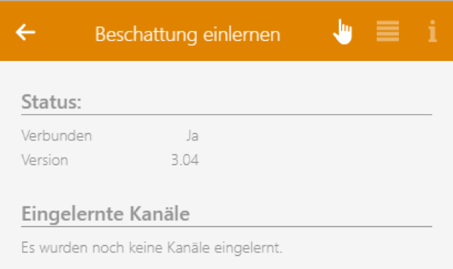
Zusätzlich muss der Stick mindestens über die Version 3.04 verfügen. Dies kann im SettingsPanel überprüft werden. Angeschlossene Erweiterungen findest Du unter "Alle Apps" - "Einstellungen" - "Schlotterer".
Wurde der Stick erfolgreich verbunden, kannst Du mit dem Einlernen neuer Kanäle beginnen. Beachte, dass maximal 10 Elemente gleichzeitig eingelernt werden können. Es dürfen somit nur maximal 10 Elemente gleichzeitig ein- und ausgesichert werden um den Einlernvorgang bei diesen Elementen zu starten.

Starte den Einlernvorgang über den Button „Neuen Kanal einlernen“. Ein einfacher Wizard führt Dich nun durch die notwendigen Schritte.

Für das neue Beschattungselement wird automatisch der nächste freie Kanal verwendet.
Außerdem wird beim Einlernvorgang automatisch erkannt, ob der Antrieb ein Rolladen-bzw. Raffstore-Motor ist. Aus dieser Information wird danach die Bedienoberfläche erstellt.

Für die Steuerung der Retrolux-Sonderfunktionen, kann nach dem Einlernvorgang in den Einstellungen der Lamellentyp ausgewählt werden. Zudem verfügt die Bedienoberfläche, je nach gewähltem Typ, über die Möglichkeit in Arbeitsstellung bzw. Geschlossene Stellung zu fahren.
Konfiguration

Bestimmung des Typs
Schlotterer Beschattungselemente sind in unterschiedlichen Ausführungen erhältlich. Je nach Typ stehen verschiedene Funktionen zur Verfügung. In den Einstellungen kann der Typ der Raffstoreelemente über die Form der Lamelle erkannt werden.
Hierfür stehen drei verschiedene Lamellentypen zur Auswahl: 80R, 80d und 92Z. Die Typen 80R und 92Z entsprechen einer herkömmlichen Jalousie, der Typ 80d entspricht einer Schlotterer Jalousie welche auch in der Ausführung mit Arbeitsstellung verfügbar ist.
Um zu erkennen welche Jalousie Du verwendest hilft Dir ein Wizard, mit dem Du anhand der Bewegung der Lamelle erkennst, um welchen Jalousie-Typ es sich handelt.

Fahrzeiten berechnen:
Alle Beschattungselemente besitzen Endpositionen, welche bei der Installation eingestellt werden. Um die korrekte Position des Elements garantieren zu können, müssen die Fahrzeiten über den Button „Fahrzeiten berechnen“ einmalig konfiguriert werden. Der Ablauf erfolgt automatisch und die Endpositionen sind anschließend korrekt eingestellt.

Verfügbare Funktionen
Rolladen
Der Rolladen bietet Funktionen zum Öffnen, Schließen, Stoppen, Positionieren und das Positionieren auf definierte Favoritenpositionen.
Die Favoritenpositionen können in den Einstellungen der Jalousie konfiguriert werden. Dabei wirst Du durch einen Wizard geführt, welcher Dich beim Einlernen unterstützt.
Standard Jalousie
Die Standard Jalousie bietet Funktionen zum Öffnen, Schließen, Stoppen, Positionieren, Tippen Auf und Tippen Zu.
80d mit Arbeitsstellung
Die Jalousie 80d mit Arbeitsstellung bietet zusätzlich zur Standard Jalousie die Funktionen „Arbeitsstellung“ und „Geschlossen“. Beim Modus „Arbeitsstellung“ bleibt die Lamelle immer der Jalousieposition entsprechend geöffnet. Im Modus „Geschlossen“ schließt die Jalousie und Lamelle komplett.
80d ohne Arbeitsstellung
Die Jalousie 80d ohne Arbeitsstellung bietet zusätzlich zur Standard Jalousie die Funktionen „Lichtlenkung“ und „Aufwenden“. Die Funktion „Lichtlenkung“ schließt die Jalousie und öffnet die Lamelle. Die Funktion „Aufwenden“ belässt die Jalousie auf der aktuellen Position und wendet die Lamelle auf.
WakeOnLAN

Die Wake On Lan App ermöglicht Dir das Aktivieren/Starten verschiedener Netzwerkgeräte (TV-Geräte, Beamer, PCs, ...) welche sich in einem Standby-Zustand befinden.
Konfiguration

Geräte welche die Wake On Lan (WOL) Funktion unterstützen erwarten den Empfang der eigenen MAC-Adresse in einer speziellen Form. Aus diesem Grund muss zur Konfiguration nur die MAC-Adresse des gewünschten Gerätes eingestellt werden. Die eingegebene MAC-Adresse wird dabei validiert, die folgenden Formate werden unterstützt:
- AA:BB:CC:DD:EE:FF
- AA-BB-CC-DD-EE-FF
- AA.BB.CC.DD.EE.FF

Die Wake On Lan Funktion muss bei einigen Geräten erst aktiviert werden. Als Beispiel wird das Aktivieren der Funktion auf einem Windows-PC erklärt. Unter Systemsteuerung -> Netzwerk und Internet -> Netzwerkverbindungen -> Adapter auswählen -> Eigenschaften -> Konfigurieren... -> Erweitert -> Wake on Magic Packet -> ENABLED.
Das Aktivieren der Funktion kann abhängig vom Gerät und Schnittstelle anders funktionieren, wird aber meistens von den Herstellern dokumentiert.
Bedienung

Durch drücken des "Wake Up!" Buttons wird die Wake On Lan Funktion für das konfigurierte Gerät (MAC-Adresse) ausgeführt.
Szenen
Die WakeOnLAN App bietet folgende Funktionen für evonHOME Szenen (Dann...):
- WakeUp: Löst den Aufwachvorgang des konfigurierten Endgerätes aus
evonHomeConnect
Mit der App "evonHOME Connect" kannst Du von einem zweiten evonHOME Werte Abfragen und Methoden aufrufen, welches sich im selben Netzwerk befindet. Damit lässt zum Beispiel das öffnen der Eingangstür eines Mehrparteien Wohnhauses umsetzen.

Du findest die "evonHOME Connect" App unter Alle Apps.
Erstellen

Um einen neuen evonHOME Connect Client zu erstellen, navigiere zur App und wähle "Client hinzufügen".
Konfiguration
In den Einstellungen kannst du Allgemeine Einstellungen für den Client vergeben, wie zum Beispiel die Verbindungsdaten.

Einstellungen
Client Aktiviert
Mit dieser Option lässt sich der Client deaktivieren damit er keine Daten mehr abfragt oder sendet.
Nicht erreichbar nach
Mit diesem Wert kannst Du einstellen nach welcher Zeit ein Client als "nicht erreichbar" gekennzeichnet wird.

Netzwerkeinstellungen
IP Adresse
Hier kannst Du die IP Adresse des zweiten evonHOMEs eingeben.
Port
Hier kannst Du den Port des zweiten evonHOMEs angeben. Standardmäßig ist dieser 80.
Benutzername
Hier kannst Du den Benutzernamen des Benutzers angeben mit welchem Du dich anmelden möchtest. Dieser Benutzer muss im zweiten evonHOME angelegt sein.
Passwort
Hier kannst Du das Passwort für den Benutzer angeben.
Farbe und Icon
Hier kannst Du eine Farbe und ein Icon für den Client vergeben werden, welche dann entsprechend angezeigt werden.
Damit die Netzwerkeinstellungen übernommen werden musst Du "Netzwerkeinstellungen übernehmen" anklicken.
In der Bedienung können über den Button "Werte auswählen" die Werte und Methoden ausgewählt werden, welche zur Verfügung stehen sollen.

Mit "App auswählen" wird ein Wizard geöffnet welcher die Verfügbaren Werte und Methoden anzeigt und ausgewählte hinzufügt. Alternativ können Werte und Methoden auch manuell angelegt werden indem Du auf "Neue Methode hinzufügen" oder "Neuen Wert hinzufügen" klickst.

Wenn Du den Wizard mit "App auswählen" startest bekommst du im ersten Schritt eine Ansicht mit allen verfügbaren Apps.

Im zweiten Schritt bekommst du eine Ansicht aller Elemente der ausgewählten App.

Im dritten Schritt bekommst Du eine Auswahl aller verfügbaren Werten und Methoden. Wählst du eine davon aus wird Dir der entsprechende Wert oder die entsprechende Methode angelegt.

Einstellungen für Werte
Attribut ID
Hier kannst Du nachträglich ändern welcher Wert abgefragt werden soll.
Zyklisch
Hier kannst du einstellen ob der Wert zyklisch abgefragt werden soll und in welchem Zyklus abgefragt werden soll.
Aktualisieren
Bei Betätigung dieses Buttons wird der Wert aktualisiert.

Einstellungen für Methoden
Methoden ID
Hier kannst Du nachträglich die Methode ändern welche aufgerufen werden soll.
Parameter hinzufügen
Hier kannst Du nachträglich Methoden Parameter hinzufügen. und Bestehende Parameter ändern.
Methode aufrufen
Hiermit kannst Du die Methode aufrufen.
Bedienung

In der Bedienung des evonHOME Connect Clients werden die ausgewählten Werte angezeigt und die Methoden können ausgeführt werden.

In der Ansicht unter "Werte anzeigen" lassen sich die Methoden ebenfalls ausführen.

Außerdem können Werte und Methoden auch an anderen Stellen deines evonHOME verwendet werden, wie zum Beispiel in Szenen oder Logikprogrammen. Hierfür bietet die Auswahl im oberen Bereich einen Reiter "evonHOME Connect" mit allen verfügbaren Clients und deren Methoden und Werten.
Szenen
Die evonHOME Connect App bietet folgende Auslöser für evonHOME Szenen (Wenn...):
- Client wurde Offline: Der verbundene evonHOME Client ist nicht mehr erreichbar
- Client wurde Online: Der verbundene evonHOME Client ist wieder erreichbar
Rest Client
Mit der App "REST Client" kannst Du auch Funktionen auf Geräten auslösen, für welche es keine eigene evonHOME App gibt, welche jedoch über eine REST Schnittstelle verfügen.
Für die Verwendung von REST benötigst Du ein Verständnis für die Funktionsweise von REST und die Schnittstellen die dir das Gerät bietet, welches du anbinden willst.
Eine kurze Beschreibung zu REST findest du hier.

Du findest die "REST Client" App unter Alle Apps.
Erstellen

Um einen neuen REST Client zu erstellen, navigiere zur App und wähle "Client hinzufügen".
Konfiguration
In den Einstellungen kannst du Allgemeine Einstellungen für den Client vergeben, wie zum Beispiel die Verbindungsdaten.

Verbindung
HTTP / HTTPS
Hier kannst Du angeben ob der REST Service über eine Verschlüsselte Verbindung (HTTPS) zur Verfügung steht oder nicht.
Host
Hier kannst Du die IP-/Web-Addresse des REST Services angeben.
Port
Hier kannst Du den Port des REST Services angeben.
Basis URL
Viele REST Services haben einen fixen Basis Pfad von welchem ausgehend alle weiteren Anfragen angehängt werden, diesen kannst Du hier mitangeben. Z.B.: "/api".
Globale Header
Hier kannst Du Header angeben welche mit jeder Anfrage mitgesendet werden sollen. Diese müssen als JSON String angegeben werden.
Authentifizierung
Es gibt drei vorhandene Authentifizierungsmethoden welche unterstützt werden: keine, Basic, Benutzerdefiniert.
keine
Wenn "keine" gewählt ist wird keine Authentifizierung vor dem Senden von Anfragen geschickt.

Basic
Bei "Basic" kannst Du einen Benutzernamen und ein Passwort mitschicken. Diese Authentifizierungsmethode kann gewählt werden wenn der REST Service Basic Authentifizierung unterstützt.

Benutzerdefiniert
Für andere Authentifizierungsmethoden gibt es die Möglichkeit einer Benutzerdefinierten Authentifizierung.
- Methode: Hier kannst Du auswählen ob die Authentifizierung über GET oder POST gesendet werden soll.
- Login URL: Hier kannst Du einen Pfad für den Login wählen, dieser ist unabhängig von der Basis URL.
- Header: Hier kannst Du Header für die Login Anfrage angeben. Diese müssen als JSON String angeben werden.
- Token: Hier kannst Du angeben ob bei der Antwort vom REST Service der benötigte Token im Header gesendet wird oder im Body.
- Position: Hier kannst Du die Position angeben an der der Token in der Antwort steht. Z.B.: "login-token" im Header.
- Inkludieren in: Hier kannst Du angeben ob der ausgelesene Token bei weiteren Anfragen im Header oder im Body mitgesendet werden soll.
- Position: Hier kannst Du die Position angeben an der der Token bei weiteren Anfragen eingefügt werden soll. Z.B.: "x-token" im Header.
- Periodisch Einloggen: Hier kannst Du angeben ob ein periodischer Login erfolgen soll und in welchem Abstand.

Damit die Einstellungen übernommen werden muss der Button "Einstellungen übernehmen" gedrückt werden.

Über den Button "Anfragen bearbeiten" kommst Du auf die Ansicht der Anfragen für den REST Client. Hier kannst Du neue Anfragen anlegen und bestehende bearbeiten.

Mit "Anfrage hinzufügen" kannst Du eine neue Anfrage erstellen.

In den Einstellungen von Anfragen kannst Du definieren was in der Anfrage gesendet werden soll.
Methode
Hier kannst Du auswählen mit welcher HTTP Methode die Anfrage gesendet werden soll.
Url
Hier kannst Du angeben auf welchen Pfad die Anfrage gesendet werden soll. Dieser wird dann zusätzlich zum Host und Basis Pfad angehängt.
Header
Hier kannst Du Header angeben welche mit der Anfrage mitgesendet werden sollen. Diese müssen als JSON String angegeben werden.
Body
Hier kannst Du angeben was im Body der Anfrage gesendet werden soll. Der Body muss als JSON String angegeben werden.
Zyklisch
Hier kannst Du angeben ob die Anfrage Zyklisch gesendet werden soll und in welchem Abstand.

Du kannst deine Anfrage mit "Anfrage schicken" senden, um zu testen ob alle Einstellungen richtig gesetzt sind und bekommst die Antwort angezeigt.
Bedienung

In der Bedienung des REST Clients werden Dir die Anfragen angezeigt und können gleich gesendet werden.

Auch unter "Anfragen bearbeiten" kannst Du die Anfragen senden.

Außerdem können die Anfragen auch an anderen Stellen deines evonHOME verwendet werden, wie zum Beispiel in den Szenen.