Configuration
Once you have connected the evonHOME app with your evonHOME, there are just a few steps to be taken in order to adapt your evonHOME to your requirements.
Once you have connected the evonHOME app with your evonHOME, there are just a few steps to be taken in order to adapt your evonHOME to your requirements.
Use the app “areas” to organize your evonHOME into rooms and elements within the rooms (e.g. lights, blinds …). This way, you will be able to find them quickly.
Your previously defined rooms will be displayed on the home screen (as long as they contain elements). To modify the rooms, open the “settings” app and select “areas, rooms”.
In order to add rooms, areas and floors to your evonHOME, simply tap on the corresponding element (e.g. “add room”). This automatically opens the operator panel for the added element. Enter the name into the field “name” and an abbreviation in the field “abbreviation” for the room. If you want to allocate this new room to a floor, simply select the floor you want. If you want to move the area back to the highest level, select the empty entry in “area, floors”.
Alternatively you can first navigate to a floor and add a room there.
If you wish to personalize your rooms, you can select colour, icon and background picture for your room. Do this by opening the operator panel for the room via in “settings” – “areas, rooms” and select the element under “settings” and modify it.
Open the area via the button “edit” and view the elements for this area. If you want a shortcut to an area, simply click on the area of the symbol in the object panel (left).
You can also link each room with a room thermostat. Do this by allocating an element to this room in the app room climate. If you have allocated more than one room thermostat to a room, you can use the parameter panel of the room to select the room thermostat you wish to use for the room temperature display.
After you have connected via the evonHOME app to your evonHOME system, you should name all of the connected devices (lights, blinds, heating circuits, etc.) and allocate them to a room. This helps you to not only find and operate them easier, but also to access further functions.
Open “lights”, “blinds” or “room climate”, depending on the items you wish to modify the names and rooms.
The app shows you a list of central functions and below that a list of your elements – this corresponds to the channels of your evonHOME modules. More detail concerning the central functions can be found in the corresponding documentation.
Tap on the area that displays the name and the room, in this case “ no name”, “no room” to open the settings for this device.
Enter the name of the device in the field “name”. You can type any name in here, or use a predefined name by tapping on the small arrow.
Tap on the field to select a room. The system already has a predefined few names that you can use. If you cannot find a suitable room in the list, create one in the settings -> areas and custom rooms.
You do not need to specifically save your changes, simply tap on the arrow symbol in the menu bar.
Choose a distinctive name depending on the device and purpose like: ceiling light, ambient, radiator or wall heating.
You can allocate different rights in your evonHOME to users, for example so that children can only use functions in the children’s room. The rights are controlled via the user groups.
You can find users and user groups in “all apps” – “settings”.
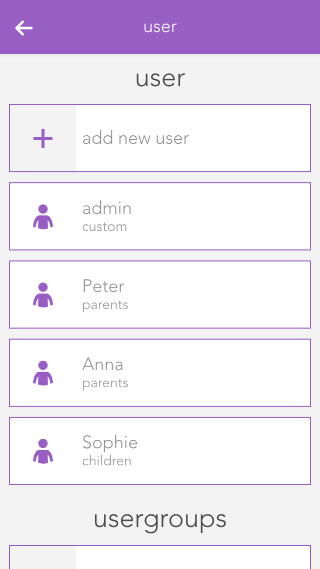
A user allows you to control exactly the rights for your evonHOME.
You can add a new user here or configure an existing one. To add a new user, simply select “add user”. This opens a panel where you can enter the user name and an optional description. Enter a password for the user so that you can login using the username.
Profile picture
The profile picture to be displayed for this user.
Background picture and text colour
You change the background of your visualization as you wish. The text colour selects the colour of titles such as “favourites” on the home screen so that they are readable, even with other background pictures.
Show areas on the home screen
This setting lets you define whether areas will be displayed on this user’s home screen.
Own favourites
If you activate the option “own favourites”, you can customize the favourites on your own home screen without these changes being visible to other users. If this option is deactivated, then your favourites are shared with other users and any changes will be visible to all users.
Language
This lets you change the language for this user. To change the language of the current user, click on “load new language settings”.
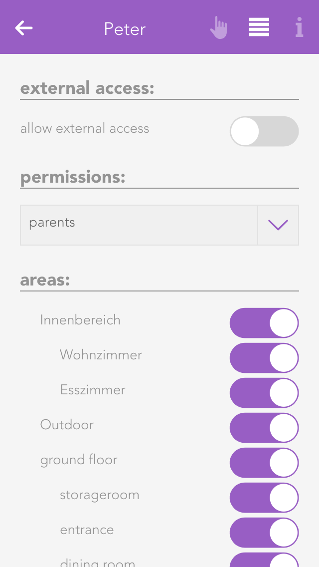
Permit external access
The option “allow external access” lets you decide whether this user is permitted to connect to your evonHOME externally.
Rights
This allows you to allocate rights to this user. If you want to allocate rights independently from a group, simply select “user defined”. The individual rights are explained further down the screen. If the user is to have no rights, simply select “no rights”.
Areas
The section “areas” lets you select which the areas this user is to have access to. If you have allocated this user to a user group, the rights in this group have already been defined for this area and hence you only have the possibility to limit the rights for individual areas further.
Some changes cannot be made to the user you have used for your login. So for example you cannot withdraw administrator rights or delete the current user.
User groups allow you to configure rights for several users.
The settings can be modified for a user group that already exists, or a new one can be created. To create a new user group, click on the element “add group”. This opens a panel where you can enter the name of the group (e.g. “guests”), and assign colour and an icon.
Rights are used to limit what a user in this group is allowed to do in your evonHOME.
Admin
This level of rights gives the user full access to all possibilities in the system. All the following rights are deactivated, since they are all included in the admin rights.
Change parameter
Users in this group are allowed to change parameters, i.e. all settings accessible via the parameter symbol.
Manage settings
The user can open the settings (all apps – settings) and make changes. Exceptions are the user settings.
Manage home screen
The user can change the start page of the app, in other words, they can set favourites and move elements. See also “own home screen”.
Add object
The user can add new objects to the system, for example a new surveillance camera, a new Denon system, etc.
Edit logic
The user can create and edit logic elements.
Edit scenes
The user can create and edit scenes; otherwise scenes can only be executed.
Edit area
The user can create and edit areas.
Execute universal scene
The user can execute universal scenes such as close all blinds, switch on all lights, etc.
See all apps
The user can open all apps, otherwise they only have the possibility to open apps that are on the home screen.
See notifications
Notifications are displayed for the user (such as wind, alarm system, etc.).
In “areas”, you can define which areas the users in the group will be able to access.
A light in evonHOME corresponds to a lighting channel that is connected to an evonHOME light module. Once connected, each light can be switched on and off. In addition, you also have the pre-defined universal functions “all lights on” and “all lights off”.
You can find the lights under “all apps”.
You can switch a light on or off via the “power symbol” on the left side. The right-hand side of the panel shows you whether the light is currently switched on or off. Clicking on the element takes you into the extended operation or configuration of this light. You can switch the light on or off by clicking on the bulb symbol.
If you have a dimmable light, you can switch in on or off via the object panel. Of course, you can also control this dimmable light via the operator panel by setting the circular slider around the light to the desired value.
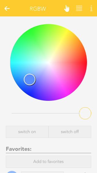
RGBW
If you own a RGBW Module (HC-L1644), you can control the desired light color and brightness from within the OperatorPanel.
Additionally, you can also save the current light settings as a favorite and activate it again later.
Saved favorites will also be displayed in the ObjectPanel, if you resize it to the appropriate size.
Once a light has been given a name, you can configure it to suit your needs.
Mode
This setting determines whether this light is controlled by a switch or a presence detector. If you select “presence detector”, the settings to adjust the time the light is switched on are displayed.
Activate daylight lock
This option lets you prevent the light from switching on during the day (if there is sufficient light). This can be used for a hallway where the light is controlled by a presence detector. You can adjust the source for daylight detection in the global settings.
Lock
If you activate “lock”, then the light cannot be switched on or off by the switch, nor by the presence detector.
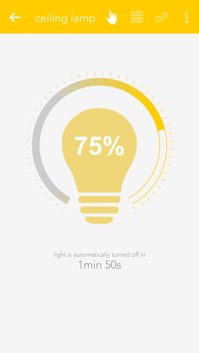
Activate energy saving mode
This option lets you configure the light to switch itself off after a certain time. If you have activated this option, then the software shows you the settings for the time the light is to remain switched on. You can change this time to anything you want.
Remove from universal scene
An example of a universal scene is “all lights off”, where all lights are switched off. However, if you want a particular light to be excepted from this, then activate this option (useful for lighting an aquarium).
Reserve
If you have a module with spare connections, i.e. where no light is connected, the app still shows that the light is on or off, because the output is active (although no light is actually connected). The “reserve” field lets you hide lights that are not used/connected. You can reactivate this light via the corresponding module in the app “hardware”.
Minimum and maximum brightness
Minimum and maximum brightness: many lights only have a noticeable change in brightness within a certain range. Hence you can set a minimum and maximum brightness level so that dimming will happen in between those limits. The visualization will still display 0% to 100%.
Fade in time
This is the time that the light is to take to reach the desired brightness from being switched off.
Dim speed
This is how fast the brightness is reached when the button is pressed continuously.
Minimum brightness
Legt die kleinste Helligkeitsstufe fest
Set the minimum brightness level
Maximum brightness
Set the maximum brightness level
Fading time
This will set the time it takes for the light to dimm between "on" and "off" state rather than switching instantly.
Dimm speed
Sets the time it takes for the light to dimm to the desired brightness.
Color changing speed
This setting will affect how fast the light switches through all available colors when using the linked switch with a longpress.
Only white
When this setting is active, the color wheel will be hidden and only the brightness slider is available in the OperatorPanel.
Enable saving energy
Enables the energy saving mode, in which the light will switch itself off after a given time. You can adjust the desired time with the given interface elements, which appear once this setting is active.
Exclude from universal scene
Activating this option will exclude it from Universal scenes which will not impact this light anymore until this option is turned off.
Switch off automatically after
This option only appears after the "enable saving energy" setting it active. It allows you to adjust the time it takes for the light to switch itself off.
While the standard mode of the RGBW Module is "1xRGBW" it is also possible to switch to "4xWhite". This will allow you to connect 4 separate lights to one RGBW module and use them like normal dimmable lights. To change this setting, go to "All apps" - "Hardware" and navigate to the correct module ("Light1644"). Click on the Name and change the setting in the appearing OperatorPanel.
You can configure settings that affect all lights in “all apps – settings – lights”.
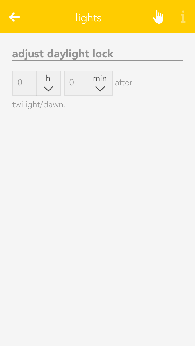
Daylight-lock-delayed switching
To configure the daylight lock, navigate to settings and select lights. You can adjust how many minutes after dusk you want the daylight lock to be deactivated and how many minutes after dawn you wish the daylight lock to be activated. In other words, if your evonHOME registers dusk at 8pm and you have set 10 minutes, then the daylight lock will be deactivated at 8:10pm.
You can find possible application examples here:
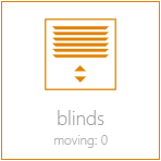
The app “Blinds” lets you operate and configure all shading elements in your system. You also have pre-defined functions such as “open all blinds” and “close all blinds”.
You can find Blinds under “all apps”.
You can open or close your shading element using the arrows in the left-hand side of the object panel. The right-hand side of the panel shows the current position and the angle of the blinds.
You can also operate each blind element via the operator panel by using the sliders on the right and on the left, or dragging the point in the middle of this window to the desired position. If you have defined a favourite position and wish to use it, simply click on the button “go to favourite position”.
Die Beschattung bietet folgende Funktionen für evonHOME Szenen (Dann...):
Beschattungselemente können unter den Einstellungen von Universalszenen ausgenommen werden. Für ausgenommene Elemente werden die Szenen-Funktionen "Alle..." nicht angewendet.
Apart from giving the shading elements individual names, you can customize them further to suit your needs.
Mode
This option is available when an 'evonHOME Blind 1344' (Schlotterer RETROLux) module is used. It allows to change the operation mode from 'standard blind' to 'without working position' or 'with working position'. In this case, 'working position' refers to a blind with a mechanical working position.
With working position
This mode is meant for use with the Schlotterer RETROLux venetian blind, which has a mechanical working position. It allows you to change the slat position with a short button press and to switch between 'closed' and 'working position'. In this mode, the slats can only be adjusted to a certain limit, which is caused by the underlying mechanical construction of these blinds.
Without working position
Choose this mode if you own a Schlotterer RETROLux venetian blind, which does not not have a working position. This mode grants you the ability to simulate a working position.
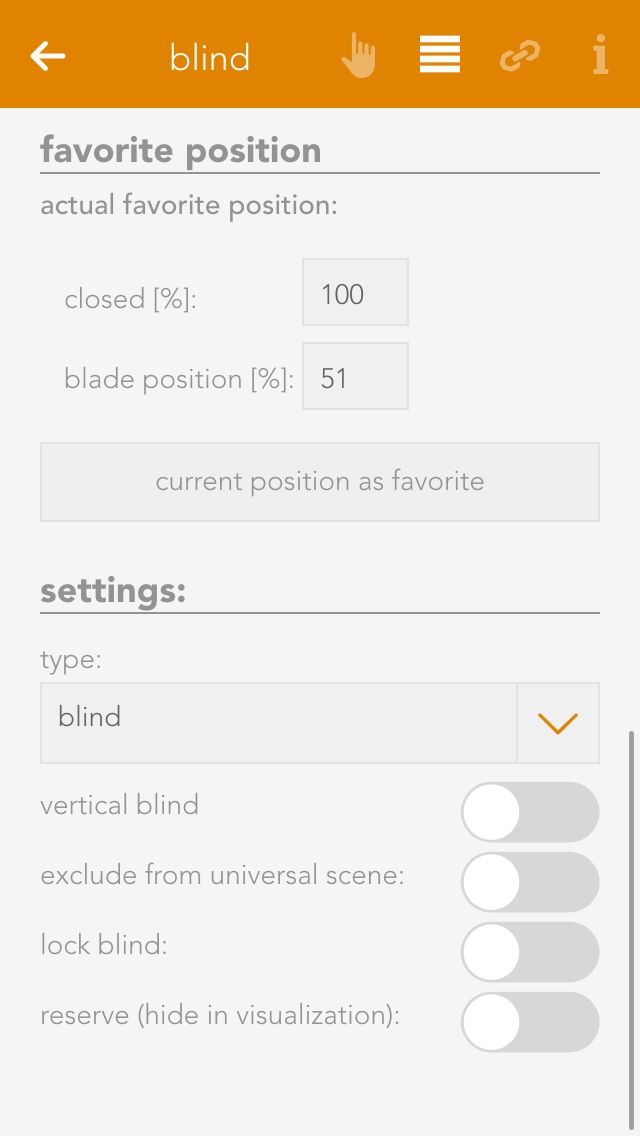
Type
Type lets you select whether the blind is a jalousie, a rolling shutter or a window (windows will be dealt with in an extra chapter). The jalousie has a position, an angle of the slats and a turnaround time, all of which must be considered in the calculation. A rolling shutter does not have an angle.
Vertical jalousie
If you have a jalousie that opens and closes vertically, then you can configure it here. If this is activated, you are then presented with a further option defining the direction you wish the jalousie to open.
Remove from universal scene
A universal scene could be “open all blinds”. However, if you want this shading element to be excepted from this universal scene, then activate this option.
Remove from wind-lock
If you do not want this blind to open in strong wind, then activate this option. If this option is not visible, then activate the wind-lock in the settings “all-apps – settings – shading”.
Lock blind
Use this option to lock a blind, which means that the shading position can no longer be changed via the app or the button.
Close at dusk
If you want the shade to close at dusk, then activate this option.
Reserve
If you have a module that has reserve connections, i.e. blinds are not connected to every output, then these elements are still displayed. The reserve function allows you to hide unused shading elements in the app. If you wish to see these unused elements, activate them in the corresponding module in the hardware section.
Extended parameter
If you use the 'evonHOME Blind 1344' module in combination with a Schlotterer venetian blind (and select the correct operation mode) additional options will be available to you here.
Those refer to the varied motion times, which are specific to Schlotterer blinds, like working position/snapping times. This settings are pre configured for optimal operation. In case you encounter any problems when switching between positions (working mode/closed) please contact your evonHOME partner, who can adjust those settings for you.
Travel time wizard
This wizard lets you easily and simply determine the travel times for your shading element. Simply follow the instructions and your travel times will be configured for you.
Use these travel times for all blinds
Pressing this button opens a dialog where you can have all blinds use these travel times. This is useful if all blinds are of the same type and you do not wish to have individual times for each blind.
You can save your favourite blind position either by entering the values by hand or pressing the button “use current position as favourite”. The favourite position can be triggered via a scene.
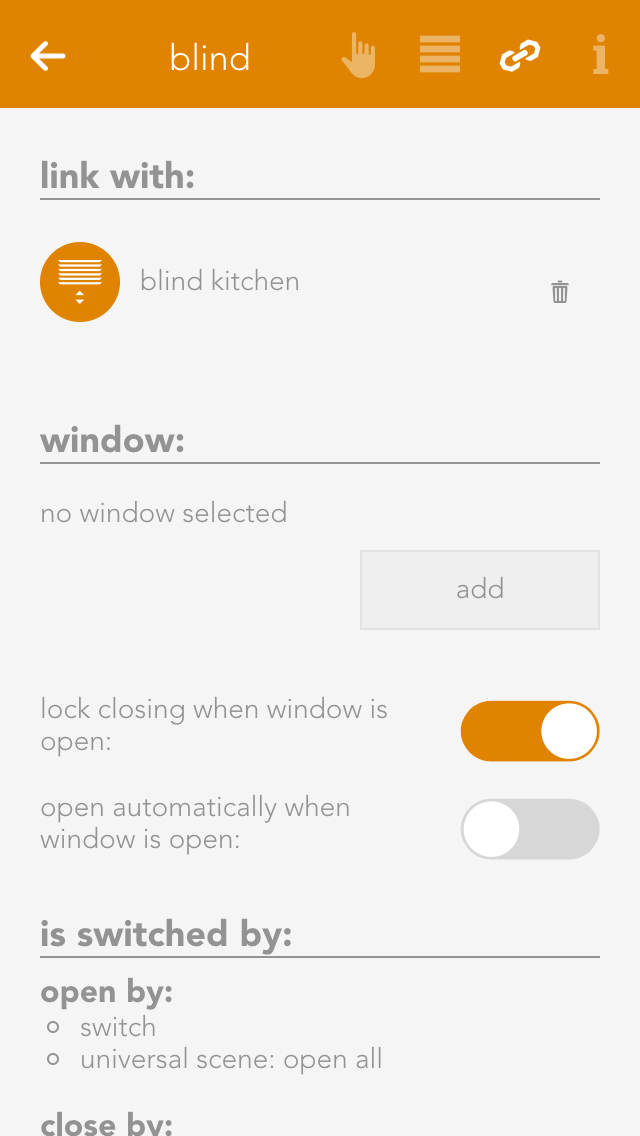
Linking allows you to connect your shading elements to other elements in your evonHOME.
Connect with
If you want two shading elements to always have the same position and slat angle, then use this “connect with”. Navigate to “connect with” and press “select” to choose the shading element you wish to connect to.
Über die Gruppenfunktion lassen sich mehrere Beschattungen zu einer Gruppe zusammenfassen. Dadurch werden alle gleichzeitig geschalten.
Um eine neue Beschattungsgruppe anzulegen, wähle "Neue Beschattungsgruppe" innerhalb der Beschattungs App.
Eine neue Beschattungsgruppe wird erstellt.
In den Einstellungen der Gruppe solltest Du als erstes einen Namen vergeben und einen Raum zuordnen.
Hier hast Du außerdem die Möglichkeit, die Gruppe zu deaktivieren. Dadurch kannst du eine bereits konfigurierte Gruppe temporär abschalten, ohne sie löschen zu müssen.
Füge nun mehrere Beschattungen hinzu. Alle Beschattungen die sich in der Gruppe befinden werden nun gleichzeitig geschalten. Schließt Du eine Beschattung der Gruppe, werden auch alle anderen geschlossen. In den Einstellungen hast Du außerdem die Möglichkeit die "Starre Kopplung" zu deaktivieren. Ist diese Funktion aktiv, fahren alle Beschattungen immer auf die selbe Zielposition und nehmen dadurch am Ende die gleiche Stellung ein. Ist sie deaktiviert, reagieren die Beschattungen nur noch auf "Auf" und "Zu" Gruppenbefehle oder auf die Befehle der verknüpften Taster in der Gruppe. Dadurch bewegen sie sich gleichzeitig, können aber dabei unterschiedliche Positionen haben.
Die Gruppenfunktion wirkt sich sowohl auf die Bedienung über die evonHOME Visualisierung, als auch Taster aus. Du kannst außerdem zu jeder Gruppe weitere Taster hinzufügen.
Settings contains the configuration for general settings that are valid for all shading element. Navigate to “all apps – settings – blinds”.
Mode
Short button press – completely up: If the blinds button is pressed for a short period of time, then the blinds will travel in the desired direction until either the blinds are fully open/closed, or a further press of the button causes them to stop where they are. A long button press sets the angle for the slats, i.e. after a wait time to correctly identify a long button press, the blind slats begin to turn until the button is released.
Short button press - set slats: A short button press changes the angle of the blinds and a long button press completely opens or closes the jalousie. A second button press interrupts the travel and the jalousie stops where it is.
Over-travel time
The over-travel time lets you define the percent of time to increase the time that the jalousie takes for completely UP to completely DOWN. This makes sure that the blinds are really open or closed.
Activate wind lock
If you have activated this option, then all shading elements are closed if it is windy. If you want to exempt elements from this wind lock, it can be done for each individual element.
Close at twilight
If “close at twilight” is selected, then all blinds will close as soon as twilight is detected. If you do not want all blinds to close at twilight, then deactivate “close at twilight” for each individual blind. In addition, you can also delay the closing at twilight by entering the number of minutes you wish to wait after twilight until the blinds close.
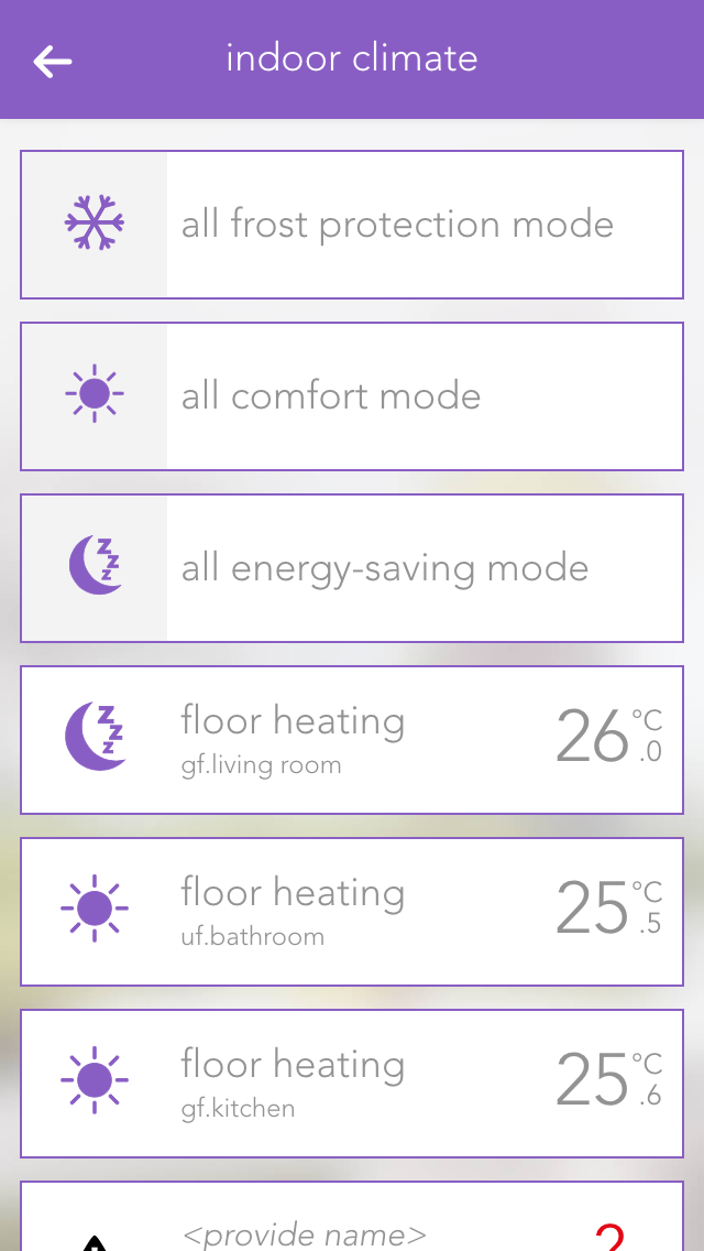
The app “indoor climate” lets you operate and configure all room climate elements in your system. You also have the pre-defined central functions “all frost protection mode”, “all comfort mode” and “all energy saving mode”.
The app is located under “all apps” – “indoor climate”.
Clicking on the left-hand area of the object panel switches back and forth between comfort mode and energy saving mode.
You can also select the operating mode using the three buttons located next to each other in the operator panel. The desired temperature can be adjusted in the circle above these buttons via the “+” and “-“ buttons, or you can simply click on the position in the circle that you want.
Deactivate individual room control
If you have a module type C1144, you can deactivate a connected room control panel with this setting. In this case, only the actual value is taken from the room control panel. All other values are ignored.
External actual value
If you have a module type C1244, you can activate this setting to receive the actual value from another source than a connected PT1000. If you use this setting, you will have to choose the new source in the linkpanel.
Cooling disabled
This setting allows you to deactivate cooling for the connected climate device. Additionally, while this option is active, the cooling mode from the global settings will also be ignored.
Permanent ON/OFF
The valve output can be permanently switched on or off, independently of the current temperature and the current operating mode.
Remove from universal scene
The valve output can be permanently switched on or off, independently of the current temperature and the current operating mode.
Display actual/desired value
This value determines whether the actual or desired value should be displayed in the object panel.
Reserve
Even if not all room climate channels are connected to a module, all four control elements are still displayed for this module. If you want to hide these unconnected control elements, then mark them as reserved. You can unhide them via the app “hardware” (all apps – “hardware”).
The desired values for the various operating modes are defined here. Clicking on the button “use this desired value for the entire room climate” opens up a dialogue with which the desired values in this room climate element can also be used for all other elements.
If the presence button on the room control panel is pressed, the desired temperature of the room is increased by the defined value and time period.
The item “temperature limit” lets you define a temperature limit, i.e. you can react with a scene if the value falls below or exceeds the limit. You can also activate notifications for falling below or exceeding the limit via “notifications for temperature limits”.
Links allow you to connect your room climate with other elements in your evonHOME.
Window contact
To ensure that heating is suspended when a window is open, you can add as many windows as you want via the button “add”. If one of these windows is opened, the heating will automatically enter into frost protection mode. As soon as the window is closed, comfort mode will be reactivated.
The settings for all room climate elements can be found under “all apps” –“settings” – “indoor climate”.
Can cool
If your heating system supports cooling, then you can activate this option. Warning! If your heating is not suitable for cooling, using this option could lead to malfunction. If in doubt, please contact a heating specialist.
Das Raumklima bietet folgende Funktionen für evonHOME Szenen (Dann...):
- Auf Energiesparen umschalten: Der Status Energiesparen wird für den Heiz -/Kühlkreis aktiv und die Sollwerte für Energiesparen werden angewendet
- Auf Frostschutz umschalten: Der Status Frostschutz wird für den Heiz -/Kühlkreis aktiv und die Sollwerte für Frostschutz werden angewendet
- Auf Komfortbetrieb umschalten: Der Status Komfortbetrieb wird für den Heiz -/Kühlkreis aktiv und die Sollwerte für Komfortbetrieb werden angewendet
A few inputs and outputs in evonHOME are used similarly in different modules. This is described in this section.
A switch can be connected to a light module, blind module or a digital module. A switch has a pre-defined function for a light or blind module. Every switch can be simulated in evonHOME for test purposes.
These switches can be found under “all apps” – “switches”.
Naming
If you have connected your switch to a light or shading module, then the switch is automatically named according to the light or blind. If you wish to give it a different name, then deactivate the option “same name as blind/light” in the parameter panel and give the switch a new name. If you have connected your switch to a digital module, then you must name it yourself.
Reserve
If you have a switch in your system that you don’t use, then you can hide it by deactivating the option “reserve “hide in display” in the app “ switches”. To unhide it, you can find your switch in the app “hardware”.
Mode
If you want to change the mode, i.e. define the switch as a presence detector or a digital input, then you can do this in the parameter panel under “mode”. Not every module can change the mode however, or not all possibilities are available. This means that the light modules’ switch can only be converted to a presence detector. Switches for a blind element cannot be converted. Switches for digital modules have all three modes.
If you have linked a switch to a scene and would now like to simulate this scene, then there is no need to go to the switch and press it every time, you can use simulation to create the switch press. Simply activate the option “simulation” in the operator panel to see 3 buttons that you can use to simulate switch presses.
Warning: If you leave the simulation mode activated, the autonomous functions will not work!
You can use the switches for a scene (assuming it as been named). In the scene “if …” just select the switch and decide if you want the scene to be executed after a single, double or long press.
Open the switches settings (“all apps” – “settings” – “switches”) if you want to define the times for a press and double-press. Select the desired values and confirm them by clicking the button “use values for all switches”.
Hold time (long button press)
A switch must be pressed for at least thus time to be recognized as a long button press.
Wait time (double-press)
The gap between two switch presses must be as least as big as the defined wait time to be recognized as a double-press.
If you wish to define different values for a switch that is connected to a blind module, then activate the option “use other values for blinds”.
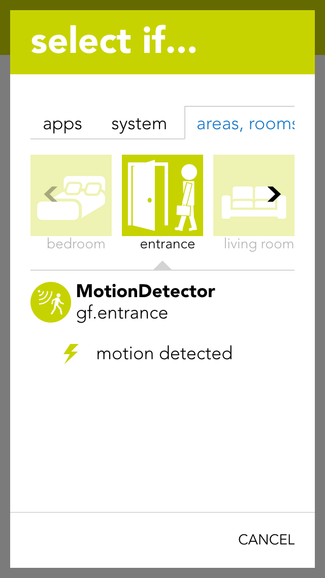
A motion detector can be connected to a light module or a digital module. The motion detector has a pre-defined function when connected to a light module. Motion detectors can be simulated in evonHOME for test purposes.
You can find motion detectors under “all apps” –“motion detectors”.
Naming
If you have connected a motion detector to a light module, then it is automatically assigned the same name as the light. If you wish to assign a different name, then deactivate the option “same name as light” in the parameter panel and enter the name you wish. If the motion detector is connected to a digital module, then you must assign it a name yourself.
Invert
If the motion detector is connected to a digital module, you have the possibility to invert the logic by activating the option “invert” in the operator panel.
Reserve
Should you have a motion detector in the system that you do not use, you can hide in from the app “motion detector” by activating the option “reserve (hide in display)” in the parameter panel. To unhide it, you will find your movement detector in the app “hardware”.
Mode
If you wish to change the mode, i.e. convert the motion detector input to a switch or a digital input, you can do this by changing the mode for the motion detector in the parameter panel. Not all modes can be changed in all modules, or not all possibilities are available. This means that a motion detector for a light module can only be changed into a button. All three modes are available for motion detectors for a digital module.
You can also use the motion detector for a scene (in as far as it has been named). In the scene, select the motion detector for “if …” and decide if you want the scene to be carried out on the rising or falling edge of the signal.
Rising edge
The electrical contact of the motion detector has been activated.
Falling edge
The electrical contact of the motion detector has been deactivated (after the internal time of the motion detector).
For example, if you have linked a motion detector to a scene and you would like to test this scene, then you do not have to go to the motion detector and activate it every time, you can change the state using simulation. Simply activate the option “simulation on” in the operator panel to see the option with which you can change the state.
Warning, if you leave the simulation switched on, the autonomous function will not work!
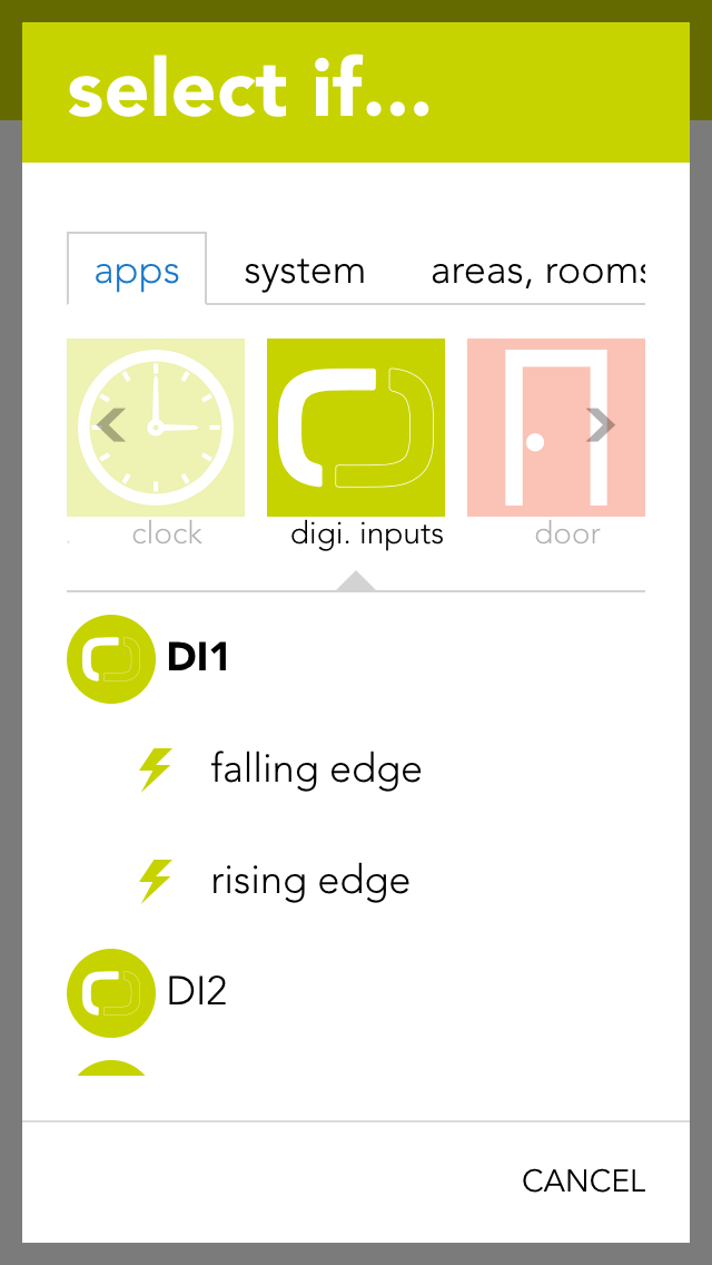
You can use a digital input for functions not provided by any evonHOME function module. You can name each digital input and simulate then for test purposes.
You can find the app “digital inputs” under “all apps” – “digital inputs”.
Reserve
If you have a digital input in your system that you are not using, you can activate the option “reserve (hide in visualization) to hide this digital input in the app “digital inputs”. (To unhide this, the digital input can be found in the hardware app)
Mode
If you wish to change the mode, i.e. convert a digital input into a button or a movement detector, this can be done in the parameter panel for the digital input under “mode”.
If you have connected a digital input to a scene and would like to test the scene, you do not have to navigate to the digital input and activate it every time, you can change it directly via simulation. To do this, activate “simulation on” in the operator panel to see the option “simulation value” with which you can change the state. Warning, once the simulation has been activated, the autonomous function will no longer work! Any changes in the state of the input “hardware” will be overwritten by the simulation.
You can also use a digital input for a scene (in as far as it has been named). Select the digital input in the scene’s “IF ….” and decide whether you want the scene to be carried out on the rising or falling edge.
Rising edge
The electrical contact of the digital input has been closed.
Falling edge
The electrical contact of the digital input has been opened.
The app “digital outputs” provides you with an overview of all digital outputs in your system. This is where you can name them and change the state of the outputs.
The app “digital outputs” is located under “all apps” – “digital outputs”.
You have two possibilities to change the state of a digital output. Either you can click on the power symbol on the left in the object panel or you can click on the button “switch” in the operator panel.
You can give a name to a digital output in the parameter panel and optionally allocate it to a room.
Save output if bus fault
If the output is active when the bus connection to the CPU fails (for example if the 24V power supply to the module fails), this option lets you guarantee that the active remains activated even in a fail state. If this option is not activated, then the output is reset after every bus connection failure.
In safety-critical controllers, it should be carefully examined whether this function should be activated, since this output is kept active if the system fails.
Mode
With the mode setting, you can change the behavior of the output once it is active. The following options exist:
Standard
This ist the normal setting for a digital output. With this, the output stays active until the signal ends.
Minimum on duration
With this mode, the output stays active for at least the specified time, even when it is deactivated before.
Pulse
In this mode, the output will automatically be deactivated after the defined timeframe.
Reserve (hide in visualization)
If you have a digital output in your system that you do not use, then you can hide this digital output in the digital output app by activating the option “reserve (hide in visualization)” (located in the parameter panel). (To unhide, the digital output can be found in the hardware app).
Change mode
If you wish to change the mode, i.e. convert a digital output to a socket, then you can do this by changing the mode for the digital output in the parameter panel.
You can also use a digital output for a scene (in as far as it has been named). In the scene’s “if …” simply select the digital output to see the following possibilities:
Switch off
The digital output is switched off.
Switch on
The digital output is switched on.
switch on for
The digital output will be switched on for a defined amount of time.
Toggle
The state of the digital output is toggled.
The app “sockets” provides an overview of all sockets in your system and allows you to name them and change their state.
The app “sockets” can be found under “all apps” – “sockets”.
You have two possibilities to change the state of a socket. Either you can click on the power symbol on the left in the object panel or you can click on the button “toggle” in the operator panel.
The parameter panel lets you give the socket a name and optionally allocate it to a room.
Save output if bus fault
If the socket is currently active and the bus connection to the CPU fails (e.g. the 24V power supply to the module fails), then activating this option will guarantee that the socket remains active even in a fail state. If this option is not activated, then the socket is reset after every bus connection failure.
In safety-critical controllers, it should be carefully examined whether this function should be activated, since this output is kept active if the system fails.
Reserve (hide in visualization)
If you have a socket in your system that you do not user, you can hide this socket in the app “sockets” by activating the option “reserve (hide in visualization) (located in the parameter panel). (To unhide, the socket can be found in the app “hardware”).
Change mode
If you want to change the mode, i.e. convert socket to a digital output, then this can be done by changing the mode in the socket’s parameter panel.
The socket can be used for a scene (in as far as it has been named). In the scene’s “if….”, select the socket and one of the following possibilities:
Switch off
The socket is switched off.
Switch on
The socket is switched on.
Switch on for
The socket is switched on for the time you define.
Toggle
The status of the socket is toggled.
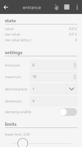
An analog input can measure voltage in the range 0-10V. This voltage is then scaled to the range defined by the user. This value can be used by the user for calculations (using logic), or simply to trigger scenes if the value exceeds or falls below certain (definable) limits.
The analog inputs are located under “all apps” – “analog inputs”.
Minimum/Maximum
Minimum and maximum limits of the measured value. These inputs must be taken from the description of the sensor used. For example, you wish to measure the humidity in a room and use a sensor with a 0-10V output signal. The sensor documentation tells you that the sensor can measure humidity from 0% to 100%. The minimum limit is hence 0 and the maximum limit is 100.
Number of decimal places
Indicates the number of decimal places used to calculate the value.
Dimension
This is where you define exactly what you wish to measure with this analog input (e.g. temperature °C).
Notification on limit violation
If the value of the analog input falls below the lower limit or exceeds the upper limit, then you will be notified by the system if this checkbox is activated.
Upper limit
Enter the upper limit here. If the value exceed this limit, you can react with a scene by selecting the trigger for “value above upper limit” in the “IF …” statement.
Lower limit
Enter the lower limit here. If the value falls below this limit, you can react with a scene by selecting the trigger for “value below upper limit” in the “IF …” statement.
Der Analoge Eingang bietet folgende Auslöser für evonHOME Szenen (Wenn...):
Raw value
A raw value is the voltage (0-10V) measured on the input of the module.
Raw value (phys.)
Corresponds to the output of an analog/digital converter and is used for the calculation into the physical measured value.
Value
Corresponds to the scaled value resulting from the raw value, minimum and maximum.
Value = (Raw value phys. / Raw value phys. MAX) * (Maximum – Minimum) + Minimum.
The Operatorpanel of the selected Analog Input also provides you with a chart, which keeps track of the measured values.
If you wish to simulate the value for an analog input, this is easily done by activating the option “simulation on” in the operator panel and selecting the desired value in the slider. This can be useful if you have defined a scene you wish to be carried out if a limit is exceed and you wish to test what happens.
An analog output outputs voltages in the range 0-10V. To do this, enter a value in your defined area and this will be output as a voltage between 0-10V.
The analog outputs can be found under “all apps” –“analog output”.
Minimum/Maximum
The calculated value is in the range between the minimum and maximum. This means that if 10V are meant to be present on the module output, then the value must be set to the defined maximum value (100%).
Number of decimal places
Defines the number of decimal places for the calculation.
Dimension
Define here what you wish to control with this analog output (e.g. speed: %)
Stored value upon bus error
If the control were to fail, the last value would be stored if you have activated this option. If you did not activate this option, the value present when the control failed will be lost.
Der Analoge Ausgang bietet folgende Funktionen für evonHOME Szenen (Dann...):
Raw value
The raw value is the voltage 0-10 V that is present (set) on the output of the module.
Raw value (phys.)
This is the digital value sent to the module.
Value
This is the scaled value that has been converted to the defined range between minimum and maximum, with the defined number of decimal places and the defined dimension.
There are two different possibilities to set a value to the analog output. Either you set the value via the operator panel for the analog output, or you select the analog output in a scene for the “if …” statement and then select “write value”. Then you can change the value by clicking on the pencil.
You can view all the module channels to which you can connect temperature sensors (e.g. PT1000) in the app “temperature”.
The temperature sensors can be found under “all apps” – “temperature”.
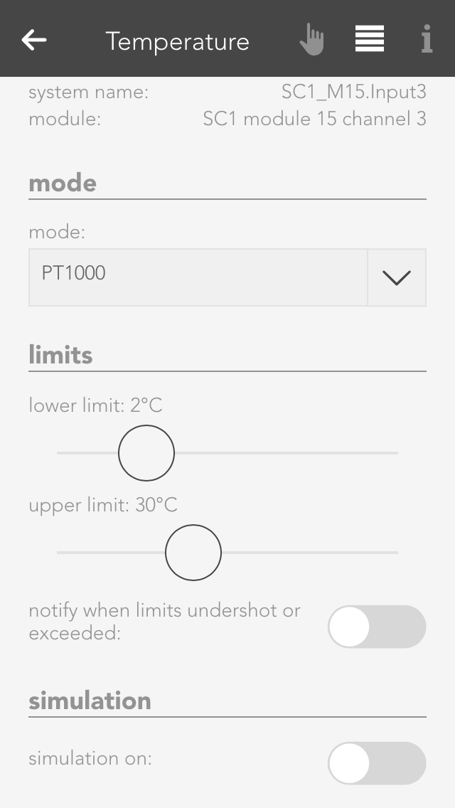
With module A1240, you can only set the temperature limits (as described in the item “scene” above). This module can only accept temperature sensors of type PT1000.
If you posses a module of type A1380, you can connect temperature sensors of type PT1000, KTY81-110 and KTY81-210. To ensure that the modules know which sensor has been connected, you must navigate to the parameter panel for this temperature sensor and select the type under “mode”.
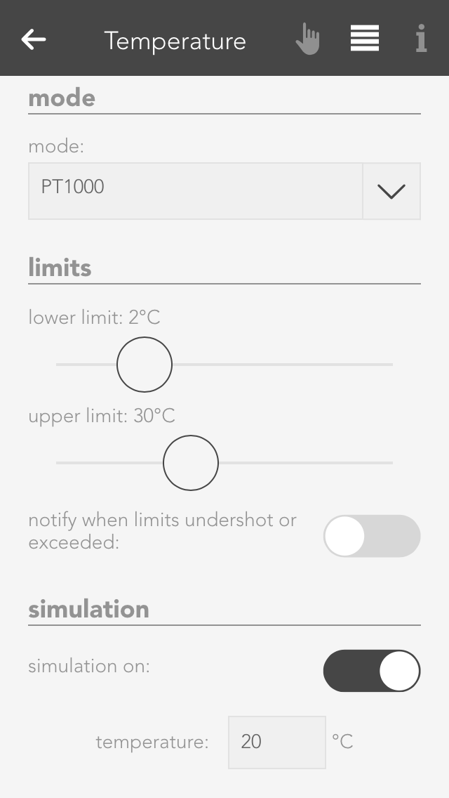
If you want to know what happens if the temperature rises above or falls below a certain value, then you don’t need to cool or heat the temperature sensor. You can use the option “simulation” in the operator panel. Simply activate the checkbox “simulation on” and enter the desired temperature in the input field that appears. Warning, do not forget to deactivate the simulation when you have finished testing.
Hier werden Dir einige Beispiele beschrieben wie Du einen Temperatursensor verwenden kannst.
Outside temperature
If you want a temperature sensor in your system to determine the outside temperature, you need to add it using the button “add” in the global settings under the item “outside temperature” and drag it to the first position. (More information in this in the documentation for global settings).
External current value for room climate zone
If you want to use this temperature sensor as an actual value for a room climate zone, then you must set the mode to “external actual value” in the desired room climate zone under “settings” and then connect the temperature sensor with it (more detail in the chapter “room climate”).
Scene
In order to link a temperature sensor with a scene, you must first allocate a name to it. Then you can set an upper and a lower temperature limit in the parameter panel that you can use in the scene for the “if …” statement. You can create a scene for the temperature falling below the lower limit or rising above the upper limit.
Logic
If you are an expert with the app “logic”, you can also use this temperature sensor here by connecting the input of a logic element with the current temperature reading.
Die Temperatur App bietet folgende Auslöser für evonHOME Szenen (Wenn...):
- Obere Grenze überschritten: Das konfigurierte obere Temperaturlimit wurde überschritten
- Untere Grenze unterschritten: Das konfigurierte untere Temperaturlimit wurde unterschritten
The general settings for your evonHOME can be found under “all apps” – “settings”.
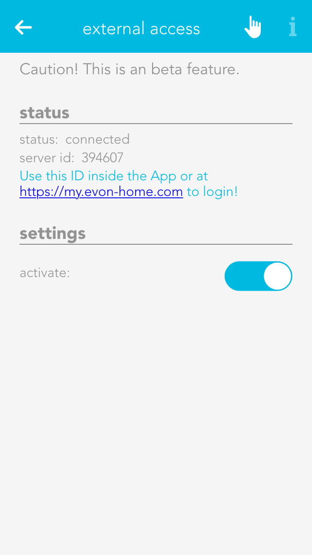
This is where you determine whether you have Internet access to your evonHOME. If external access is active, then you can access your evonHOME using your evonHOME ID from anywhere.
Global settings let you define what is responsible in your evonHOME for activating wind, rain, frost, dusk states. For example, if you have connected a rain sensor, this is where you would find the settings for your system to display whether it is raining or not. The global settings can be found under “all apps” – “settings”.
You can connect the rain sensor to the appropriate input of the iX800 controller. IF you also have a weather station or Internet weather, then you need to select which element invokes “rain” in the system. Simply drag the box with the text “iX800” in the item rain to the first place (if more than one box is available) to be able to use the controller’s rain sensor input.
If you have connected your rain sensor to a digital input, then you can select it using the button “add” and drag it to the first position.
The dusk sensor can be connected to the dusk input on the iX800 controller. If you also have a weather station or Internet weather, then you need to select which element invokes “dawn/dusk” in the system. Simply drag the box with the text “iX800” in the item dusk to the first position (if more than one box is available) to use the dusk input on the controller.
If you have connected your dusk sensor to a digital input, then you can select it via the button “add” and drag it to the first position.
Connect your wind contact to the wind input on the iX800 controller. If you also have a weather station or Internet weather, then select which element invokes “wind alarm” in your system. Drag the box with the text “iX800” in the item wind to the first position (if more than one box is available) to use the wind contact on the controller.
If you have connected your wind contact to a digital input, then select it using the button “add” and drag it to the first position.
You can select the value you wish to use for the outside temperature by dragging the element to the first position in the item outside temperature.
If you wish to measure the outside temperature using a sensor, you can do this by clicking the button “add”.
In addition, you can define a value for the frost and heat warning (in the parameter panel). As soon as the outside temperature rises above or below this value, a scene or a notification will be invoked.
The sunrise and sunset times can be calculated using the geo-coordinates. These times are then used for the dawn/dusk calculations. To make sure that the dawn/dusk calculation is performed using the geo-coordinates, drag it to the first position in the item dawn/dusk.
The geo-coordinates can be entered using the decimal point format. To find out which geo-coordinates your house has, simply go to www.maps.google.at and search for your house. Right-mouse click on your location and select “what is here?” to display your geo-coordinates (the first value is north and the second east).
If you wish to change the calculated times then activate the option “adjust time for dawn/dusk”. This will let you adjust how many minutes earlier or later you wish dawn and dusk to be.
If you wish to simulate what happens if it rains, for example, then you can simply simulate the occurrence of rain by activating the option “simulate rain” in the item “rain” and then activate the option “rain on”. This is also true for wind, outside temperature and daylight. Warning, do not forget to end the simulation when you no longer need it (e.g. deactivate “rain simulation”).
You can define which events for you would like to receive notification of in the parameter panel.
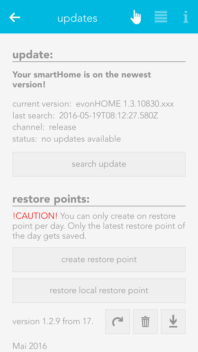
The updates screen lets you make sure your evonHOME is up-to-date. Simply click the button “search for updates” and if an update is available, click “execute update”. If you wish your system to automatically search for updates, activate the setting “search for updates automatically” in the operator panel. You can also see the current version and the time of the last update and the update channel here.
Furthermore, you can create recovery points, which allow you to reset your evonHOME to an earlier state if you have inadvertently maladjusted parameters. Such recovery points are recommended once you have named all your lights, blinds, etc. and have set them up as you require. Use the button “reset to factory setting” to reset your evonHOME to the original factory settings.
Saved recovery points will be shown in a list, where you can delete, recover, or download them at any time.
You can create one recovery point per day. If you create more, only the last one will be saved. In addition, you can also restore your system with a downloaded recovery file by using the button 'restore local restore point'.
A recovery point of your current configuration is created automatically before every update.
Project name
You can give your evonHOME any name you like in the system settings.
Controller new start
This function restarts your system. Note that while the system is restarting, you do not have a connection to the CPU.
Manifest
This item shows you whether your visualization is up-to-date. The setting “automatic reload” lets you update your visualization automatically if it is not up-to-date.
All information pertaining to your system can be found under the item system diagnostics, such as current version, memory used, IP address, etc.
You can also look at cycle times. This is an indication of the load on your evonHOME system. You can also see the last five peak values. The cycle time is the time required for a complete run of the program.
“Time” lets you see the current time and date used in your controller (server time), the time zone your controller is in and the time of the device you have used to connect to your evonHOME (mobile phone, tablet …).
The time zone lets you allocate the desired time zone to your controller. The item “set time” allows you to set the time in the controller. The button “use client time” allocates the time used by your device (mobile phone, tablet) to the controller. The button “set time manually” lets you set the time and the date for your controller yourself.
This area contains all network settings for the network used by your evonHOME. You can also configure whether the IP address and DNS server should be automatically allocated, or whether you wish to define them yourself.
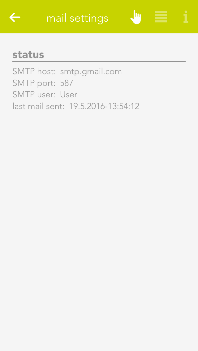
This app lets you send email notifications via an existing email account. The “test mail” function is used to test the configured settings. You will need to obtain the required settings for the SMTP server from your email provider.
You can either send a test email or you can select “send email” in the “system” tab in a scene “if …” statement. Then all you need to do is enter the sender, recipient, subject and text.
If you wish to register with your Gmail account, then you must allow “less secure apps” in your Gmail account. Simply open the link to the Google Config and click “activate”.
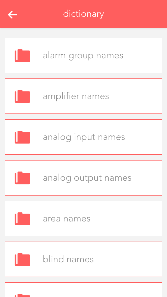
You can edit the pre-defined names in the dictionary. These names will be suggested to you when you wish to name a light, a blind, etc. However, you can even select a different name when naming your elements. The names in the dictionary are only a guide.
The “devices” app shows you all mobile devices that have been registered in your system.
The “devices” app is under “all apps” – “settings” – “devices”.
If you open a device, the display shows you the name and model of the device in the operator panel. The parameter panel shows detailed information concerning the device.
If you wish to receive notifications on this device (e.g. window is open), then you need to activate the checkbox “receive push notifications”.
The hardware app lists all modules that are connected to your system. If you wish to obtain a list of module channels, then all elements in this module are clearly displayed and in the correct order, the way they are connected to the module. This view can make it much simpler for you to name the individual elements, since you immediately know which module and which channel you wish to name.
The hardware app is located under “all apps” – “hardware”.
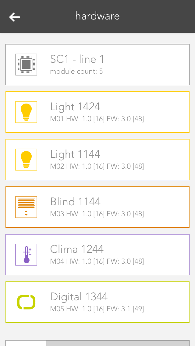
Hierarchically above the modules, you can see which line the module is located in (e.g. SC1 – line 1).
If you open the line, the first thing you will see at the top is general information about the line. The item “cycle time” lets you define the cycle time for your bus line (standard is 200 ms). “Required cycle time” shows the time that is required for the operations. “Total cycle time” is the time required by the bus for a cycle. “Peak” is the peak value of the cycle time. This can be reset using the button “reset peak”.
By opening a module (click on the right-hand area), you will see all necessary information pertaining to this module. The button “display channels” displays the available channels in this module. The button “reset” resets a module, meaning that this module is reset to factors settings.
Click on the left-hand are of the object panel or on the button “displays channels) in the operator panel to see a list of module channels. Taking a light module as an example, you will be able to see the four channels with their corresponding button/movement detector and a light. This is the exact order that the button/movement detector and light are connected to the module, i.e. channel 1 is the light that is connected on the far left of the module.