Logic Elements
Elements are all logic elements that you can add to a logic program (AND, OR, etc.)
Elements are all logic elements that you can add to a logic program (AND, OR, etc.)
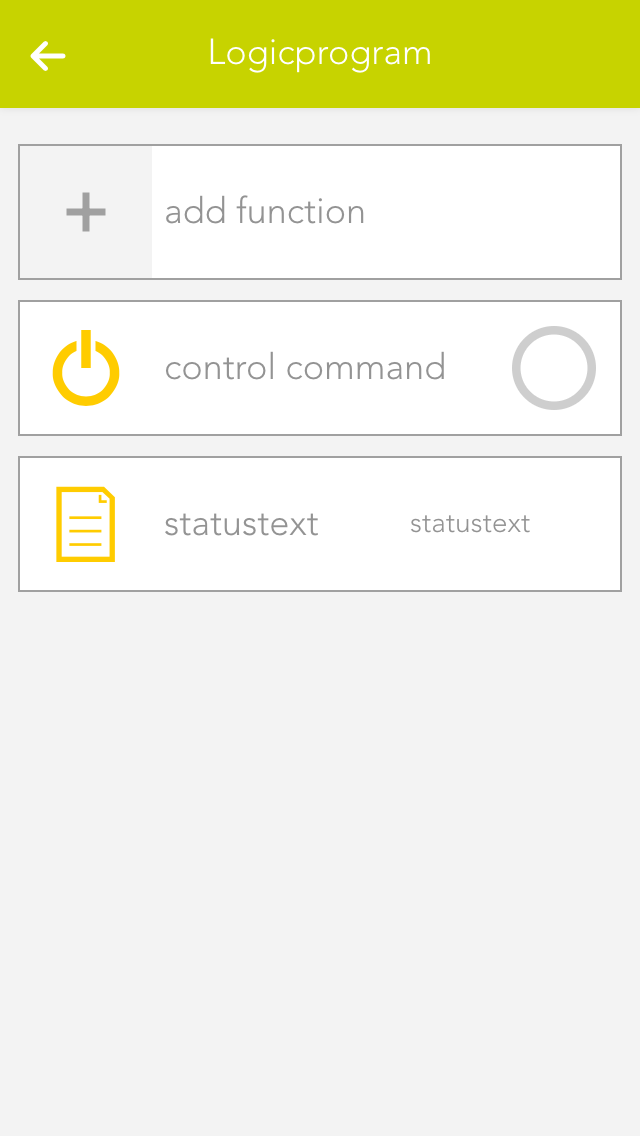
To create a logic element, you must first be located in the logic program. If not, open the logic program and select the item “edit logic” in the parameter panel. Then add new logic elements to the program using “add function”. To do this, click on the corresponding element.
If a logic element has an error, or if it is simply not activated, then you can recognize this due to the colour of the element.
Green
The element is working fine.
Orange
The output of this element is being simulated.
Grey
The element does not have a fault, but it is deactivated.
Red
The element has a fault: either an input has no value, or the output it is linked to no longer exists.
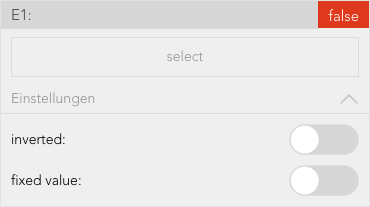
The operator panels for each logic element (except for data elements) are all constructed using the same principle. The first item is the setting (if available), then the inputs, then the output.
This shows you the selection of an input.
The button “select” lets you select the output of a different logic element that you wish to connect to this input.
The checkbox under “invert” lets you invert the input (if it is of type bool).
The checkbox under “fixed value” lets you allocate a fixed value to the input. This means that if you activate this checkbox, the type bool displays a checkbox in the centre with the text “value”. The state of the input can be controlled using this value. If you activate this checkbox for an input of data type number or string, then an input field appears where you can enter the desired value.
Data elements are intermediate stores for values. This means that data elements can be described by other logic elements by selecting this data element at the output (however only if both are of the same type). Data elements can also be linked with inputs of other logic elements. Every data element has the option “parameter” in the operator panel. If you have activated this option, then you can see this data element in the operator panel of the corresponding logic group and you can change it from there. This has the advantage that you do not always have to have the logic program open to change a value. Parameters also means that the value of a data element remains even if the controller were to fail.
You can change the value of any data element via the object panel. You can do this on the left-hand side of the object panel for types bool and number, and on the right-hand side via the input field for type string.
The element “AND” is a classical AND operator. This means the output is set to true as soon as ALL inputs are true. This element can have between 2 and 6 inputs. The number of inputs can be changed via the operator panel using the buttons “add pin” and “remove pin”.
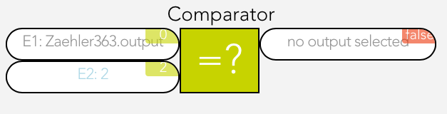
The compare function works by comparing the values present at the two inputs and switches the output accordingly.
You can change the following settings in the operator panel:
Type
Select the type of comparison
Hysteresis
If you require hysteresis, you can define it here.
Sample time
This is the time for which the comparison must be fulfilled for the output to be switched to true.
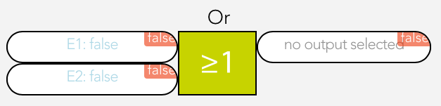
The element “OR” is a classical OR operator. This means the output is true as soon as at least one input is true. This element can have between 2 and 6 inputs. The number of inputs can be changed in the operator panel using the buttons “add pin” and “remove pin”.
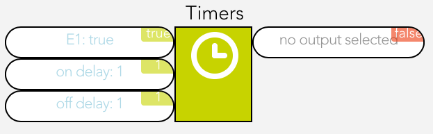
The time relay lets you delay an output switching on or off, or leave it switched on for a certain time.
The time relay has two types that you can configure under “select used times”.
Delay switching on/off
If the input is true, the output is only set to true after the selected ON time delay. If the input jumps from true to false, the output is set to false after the selected OFF time delay.
Switch on delay and duration
This enables the option “input as flank”. If you have not activated this option, then the input must be true for at least the switch on delay time in order for the output to be set true for the defined duration and after this duration (independently of the input) reset to false. If you have activated this option then a flank is sufficient on the input and the output is set to true for the defined duration and then reset to false.
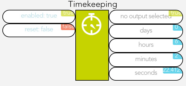
Time measurement is represented by a stopwatch. Time measurement can be started, stopped and reset via inputs “activated” and “reset”.
If the input “activated” moves from false to true, the stopwatch starts. If the input “activated” moves from true to false, the stopwatch stops, if “auto reset” was NOT activated.
If “auto reset” is activated, then the stopwatch is reset when the input “activated” moves from true to false.
The input “reset” resets the stopwatch. This only works if “auto reset” has not been activated.
Mit der Wertzuweisung kann ein beliebiger Wert dem Ausgang zugewiesen werden.
The value on the input E1 is written unchanged to the output if “activated” is true.
Der Bedingungsblock ermöglicht es, Werte nur dann zu setzen, wenn definierte Bedingungen erfüllt sind. Sollte keine Bedingung zutreffen kann zusätzlich ein optionaler Standardwert benutzt werden.
Sobald eine Bedingung true ist, werden alle Bedingungen danach ignoriert.
Eingänge:
Es können auch weitere Bedingungen mit Wert hinzufügt oder gelöscht werden, welche dann als Sonst wenn und Wert angezeigt werden.
Einstellungen:
Ausgänge:
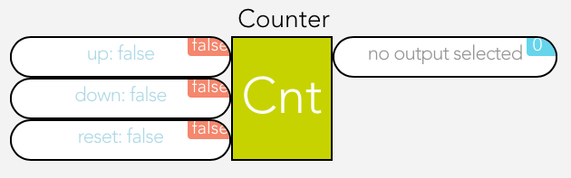
The counter can increase, decrease or reset a numerical value to 0.
The input “up” increments the counter by one when the input changes from false to true, the input “down” decrements the counter by one and “reset” resets the counter to 0.
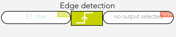
Flank recognition allows rising and falling edges to be evaluated. This means that if the selected flank appears on the input, then the output is set to true for one cycle and then reset to false.
The type of flank can be selected in the operator panel under the item “settings”.
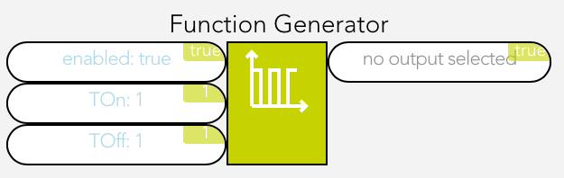
The function generator enables periodic square wave signals to be generated.
As soon as the input “activated” is true, the function generator is started and generates a periodic square wave signal on the output.
“TOn” can be used to adjust how long the square wave signal is true and “TOff” how long it is false.
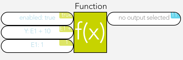
A function element is used to carry out mathematical calculations. “A1” must contain the desired calculation.
The variables E1 to E6 can be used for the calculation, e.g. A1 = 2*E1 + E2.
As soon as the input “activated” is active, the calculation will be carried out. The buttons “add pin” and “remove pin” can be used to add up to 6 inputs. The following shows link shows you which operations are possible:
Documentation- Functions(https://developer.mozilla.org/de/docs/Web/JavaScript/Reference/Global_Objects/Math)
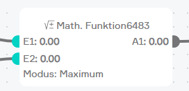
Mit dem Math. Funktionsblock können vordefinierte mathematische Berechnungen durchgeführt werden.
Folgende Funktionen stehen zur Verfügung:
This is a clocked PI controller where you supply demand value, actual value and clock.
The settings for the PI controller are located in the parameter panel.
For as long as the input is true, the output of the reset element will be set to false.
The SR flip flop is used to set and reset an output. If the input “set” is true, then the output is true. If the input “reset” is true, the output is false. If both inputs are true, then the output is false. If both inputs are false, the output is stored, meaning it remains in this state until the input is true again.
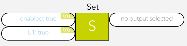
For as long as the input is true, the output of the set element will be set to true.
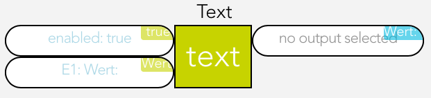
The text block is used to create any text string you want.
1 to 6 inputs (E1 – E6) can be created using the buttons “add pin” and “remove pin” and the text from these inputs are then strung together.
For example, if the text for E1 is “It is now ” and the text for E2 is the current time (use the button “select” and under “system” then “time”), then the following text string will be created “It is now 17:00”.