The logic app enables you to execute complex operations for which there is no app. For example, this could be controlling the ventilation of the WC, controlling a light transformer etc. If you wish to use logic, then you should already have a basic understanding. If you are new to the area of logic, exercise caution when using this feature.
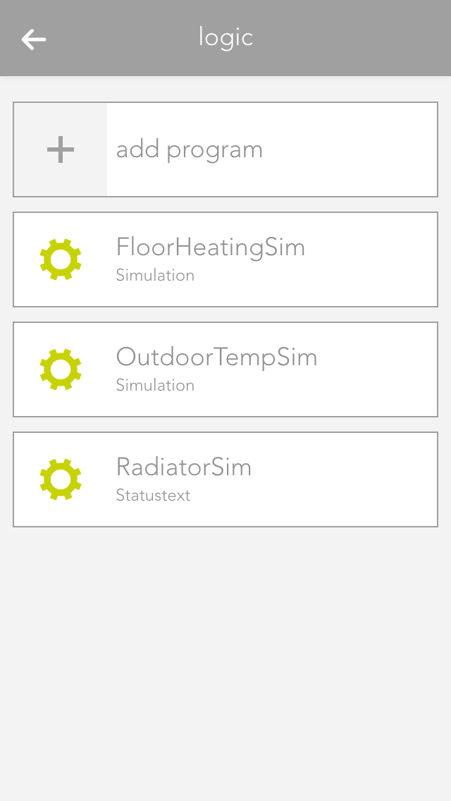
The logic app is located under “all apps” – “logic”.
Logic Program
To create a logic sequence, you first need a logic program. This is comparable to a network in PLC programming. A program contains logic elements that you can use for your controller. For example, if you have a controller for the WC ventilation and one for a light transformer, then you can create an individual program for every controller.
Create
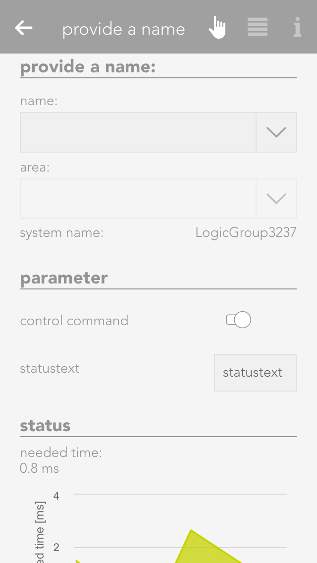
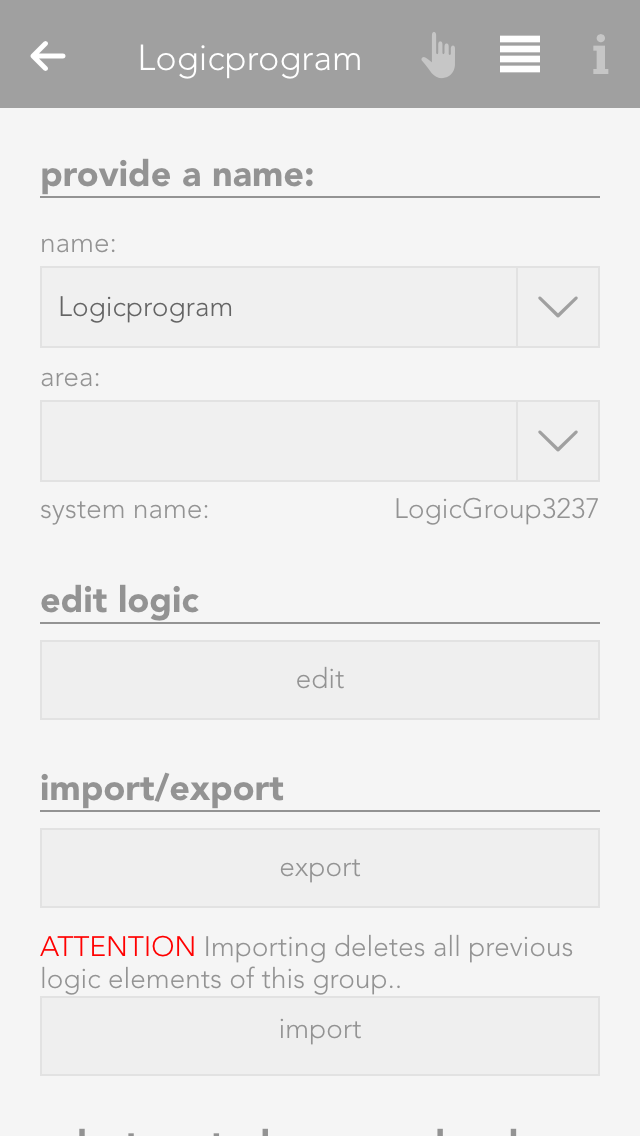
To create a logic program, open “logic” and select “add program”. This opens the operator panel for the logic program. You must first allocate a name to your program and optionally a room for it.
Parameter
The operator panel for the logic program contains an item “parameter” where all parameters available to rapidly configure the program are listed (parameters are described in the chapter data elements). The values of these parameters are not lost if a controller fails.
Status
The item “status” displays a diagram that shows you the time required to execute this program.
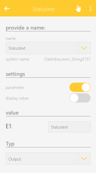
Control Command And Status Text
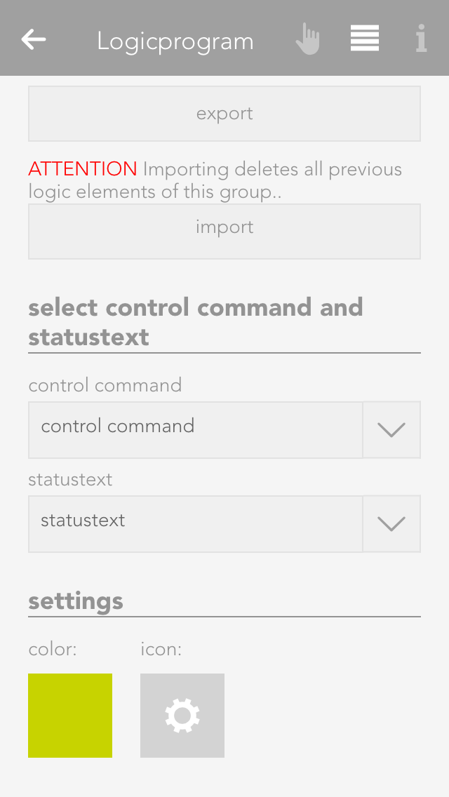
Every logic program can contain a control command and a status text. You can select a data element of type bool for the control command and a data element of type string (text). To do this, go to the parameter panel and select “choose control command and status text”.
The control command is intended to activate and deactivate the logic program via the object panel. You can toggle the control command via the icon on the left-hand side of the object panel.
The status text is displayed in the object panel under the name of the program. An example would be “ventilation will be switched off in 2 mins”.
Edit Logic
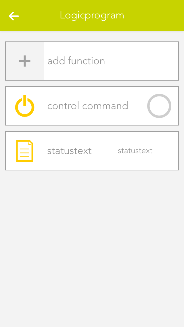
If you want to edit the logic in this program, click on the button “edit” in the parameter panel under the item “logic”.
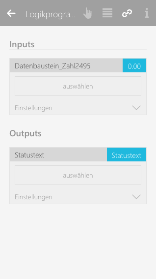
Input und Output
Each logic program allows you to define in- and outputs, which are shown in the linkpanel of a program. Defined in- and outputs can then be linked to values of other evon Smart Home apps.
This makes it possible to create interfaces for your logic program which make it easy for you to integrate it without the need to modify or edit the underlying logic construct. It is also very useful if you want to reuse it for different purposes as you only have to adapt the linked values.
To define an in- or output for your logic program, select a data element and change the type to "Input" or "Output".
It will then be listed in the linkpanel of your logic program and can be connected to other apps/values.
Import/export
If you wish to save the logic program, you can do this via the button “export” in the parameter panel under the item “import/export”.
To import a logic program, click on the button “import” (directly under the “export” button). Note that any existing logic is overwritten by the logic in the imported program. Furthermore, if logic elements were linked across programs prior to export, after importing, the links no longer exist.
Color And Icon
You can allocate a colour and icon to your logic program. Do this in the parameter panel under the item “settings” by clicking on the current colour or icon.
Szenen
Die Logik bietet folgende Auslöser für evon Smart Home Szenen (Wenn...):
(Datenbaustein Zahl): Zählerstand wurde vergrößert: Der Wert im Datenbaustein wurde erhöht
(Datenbaustein Zahl): Zählerstand wurde verkleinert: Der Wert im Datenbaustein wurde verringert
(Datenbaustein Text): Text wurde geändert: Der Text im Datenbaustein wurde geändert
(Datenbaustein Bool): Steigende Flanke: Der Wert wurde auf logisch 1 (true) gesetzt
(Datenbaustein Bool): Fallende Flanke: Der Wert wurde auf logisch 0 (false) gesetzt
Die Logik bietet folgende Funktionen für evon Smart Home Szenen (Dann...):
(Datenbaustein Zahl): Wert setzen: Der Wert im Datenbaustein kann beliebig manipuliert werden
(Datenbaustein Text): Wert setzen: Der Text im Datenbaustein kann beliebig manipuliert werden
(Datenbaustein Bool): Aktivieren: Der Wert wird auf logisch 1 (true) gesetzt
(Datenbaustein Bool): Deaktivieren: Der Wert wird auf logisch 0 (false) gesetzt
(Logikprogramm): Logikprogramm aktivieren: Das Logikprogramm wird aktiviert
(Logikprogramm): Logikprogramm deaktivieren: Das Logikprogramm wird deaktiviert
Szenenfunktionen für Bausteine (wie z.B.: Datenbaustein Zahl, Text,...) sind unter dem Reiter "Logik" und der entsprechenden Logik zu finden. Szenenfunktionen für das Logikprogramm selbst sind unter dem Reiter "Apps" und der App "Logik" zu finden.
Logic Elements
Elements are all logic elements that you can add to a logic program (AND, OR, etc.)
Create
To create a logic element, you must first be located in the logic program. If not, open the logic program and select the item “edit logic” in the parameter panel. Then add new logic elements to the program using “add function”. To do this, click on the corresponding element.
Element Colour
If a logic element has an error, or if it is simply not activated, then you can recognize this due to the colour of the element.
Green
The element is working fine.
Orange
The output of this element is being simulated.
Grey
The element does not have a fault, but it is deactivated.
Red
The element has a fault: either an input has no value, or the output it is linked to no longer exists.
Connecting Elements
The operator panels for each logic element (except for data elements) are all constructed using the same principle. The first item is the setting (if available), then the inputs, then the output.
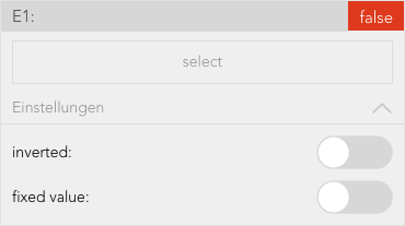
This shows you the selection of an input.
The button “select” lets you select the output of a different logic element that you wish to connect to this input.
The checkbox under “invert” lets you invert the input (if it is of type bool).
The checkbox under “fixed value” lets you allocate a fixed value to the input. This means that if you activate this checkbox, the type bool displays a checkbox in the centre with the text “value”. The state of the input can be controlled using this value. If you activate this checkbox for an input of data type number or string, then an input field appears where you can enter the desired value.
Data Elements
Data elements are intermediate stores for values. This means that data elements can be described by other logic elements by selecting this data element at the output (however only if both are of the same type). Data elements can also be linked with inputs of other logic elements. Every data element has the option “parameter” in the operator panel. If you have activated this option, then you can see this data element in the operator panel of the corresponding logic group and you can change it from there. This has the advantage that you do not always have to have the logic program open to change a value. Parameters also means that the value of a data element remains even if the controller were to fail.
You can change the value of any data element via the object panel. You can do this on the left-hand side of the object panel for types bool and number, and on the right-hand side via the input field for type string.
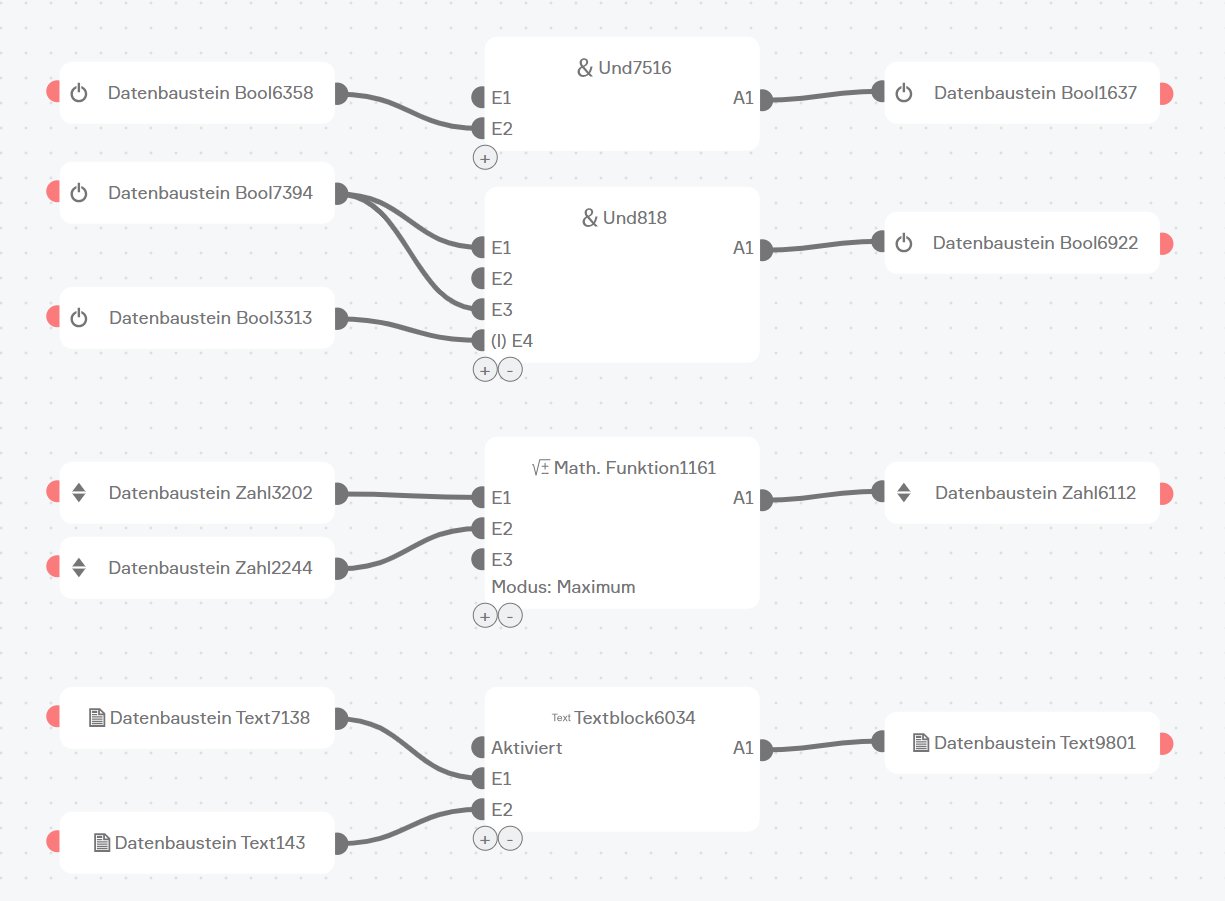
AND
The element “AND” is a classical AND operator. This means the output is set to true as soon as ALL inputs are true. This element can have between 2 and 6 inputs. The number of inputs can be changed via the operator panel using the buttons “add pin” and “remove pin”.
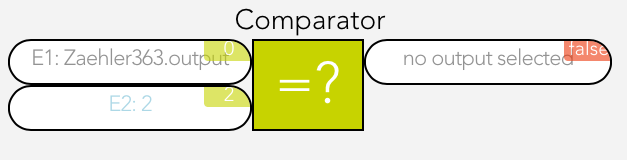
Compare
The compare function works by comparing the values present at the two inputs and switches the output accordingly.
You can change the following settings in the operator panel:
Type
Select the type of comparison
Hysteresis
If you require hysteresis, you can define it here.
Sample time
This is the time for which the comparison must be fulfilled for the output to be switched to true.
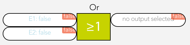
OR
The element “OR” is a classical OR operator. This means the output is true as soon as at least one input is true. This element can have between 2 and 6 inputs. The number of inputs can be changed in the operator panel using the buttons “add pin” and “remove pin”.
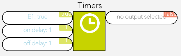
Time Relay
The time relay lets you delay an output switching on or off, or leave it switched on for a certain time.
The time relay has two types that you can configure under “select used times”.
Delay switching on/off
If the input is true, the output is only set to true after the selected ON time delay. If the input jumps from true to false, the output is set to false after the selected OFF time delay.
Switch on delay and duration
This enables the option “input as flank”. If you have not activated this option, then the input must be true for at least the switch on delay time in order for the output to be set true for the defined duration and after this duration (independently of the input) reset to false. If you have activated this option then a flank is sufficient on the input and the output is set to true for the defined duration and then reset to false.
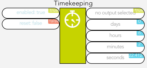
Time Measurement
Time measurement is represented by a stopwatch. Time measurement can be started, stopped and reset via inputs “activated” and “reset”.
If the input “activated” moves from false to true, the stopwatch starts. If the input “activated” moves from true to false, the stopwatch stops, if “auto reset” was NOT activated.
If “auto reset” is activated, then the stopwatch is reset when the input “activated” moves from true to false.
The input “reset” resets the stopwatch. This only works if “auto reset” has not been activated.
Value Allocation
Mit der Wertzuweisung kann ein beliebiger Wert dem Ausgang zugewiesen werden.
The value on the input E1 is written unchanged to the output if “activated” is true.
Bedingung
Der Bedingungsblock ermöglicht es, Werte nur dann zu setzen, wenn definierte Bedingungen erfüllt sind. Sollte keine Bedingung zutreffen kann zusätzlich ein optionaler Standardwert benutzt werden.
Sobald eine Bedingung true ist, werden alle Bedingungen danach ignoriert.
Eingänge:
Standardwert:
Wert welcher auf den Ausgang A geschrieben werden soll, wenn keine Bedingung zutrifft und die Einstellung Standardwert verwenden aktiviert ist
In der mobilen Ansicht kann Standardwert im Operator Panel ausgewählt werden.
In der Editor Ansicht muss zuerst rechts oben auf Bearbeiten geklickt werden. Danach kann Standardwert mit dem jeweiligen Block verbunden werden. Durch einen Klick auf den Pin links von Standardwert kann ein Fixwert zugewiesen werden.
Wenn ODER Sonst wenn:
Hier muss ein boolscher Wert verknüpft werden. Falls dieser Eingang auf true ist, wird der Wert der unterhalb definiert wurde, auf den Ausgang A geschrieben.
In der mobilen Ansicht kann Wenn im Operator Panel ausgewählt werden.
In der Editor Ansicht muss zuerst rechts oben auf Bearbeiten geklickt werden. Danach kann Wenn mit dem jeweiligen Block verbunden werden. Durch einen Klick auf den Pin links von Wenn kann ein Fixwert zugewiesen werden.
Wert:
Wert welcher auf den Ausgang A geschrieben werden soll, wenn die Bedingung oberhalb zutrifft
In der mobilen Ansicht kann Wert im Operator Panel ausgewählt werden.
In der Editor Ansicht muss zuerst rechts oben auf Bearbeiten geklickt werden. Danach kann Wert mit dem jeweiligen Block verbunden werden. Durch einen Klick auf den Pin links von Wert kann ein Fixwert zugewiesen werden.
Es können auch weitere Bedingungen mit Wert hinzufügt oder gelöscht werden, welche dann als Sonst wenn und Wert angezeigt werden.
In der mobilen Ansicht im Operator Panel, unter Eingängen mit einem Klick auf Pin hinzufügen oder Pin löschen.
In der Editor Ansicht muss zuerst rechts oben auf Bearbeiten geklickt werden. Danach kann dies in der linken unteren Ecke des Blocks mit einem Klick auf das Plus- und Minus-Icon gemacht werden.
Einstellungen:
Standardwert verwenden:
Wenn true, dann wird sobald keine Bedingung zutrifft, der Wert des Eingangs Standardwert auf den Ausgang A geschrieben.
In der mobilen Ansicht kann Standardwert verwenden im Operator Panel unter Eingänge definiert werden.
In der Editor Ansicht kann Standardwert verwenden im Operator Panel definiert werden.
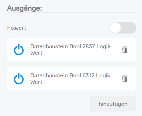
Ausgänge:
A:
Hier können beliebig viele Blöcke verknüpft werden, auf welche der Wert der ersten Bedingung welche true ist, geschrieben werden soll.
In der mobilen Ansicht kann A im Operator Panel verknüpft und ein Fixwert vergeben werden.
In der Editor Ansicht muss zuerst rechts oben auf Bearbeiten geklickt werden. Danach kann A1 mit den jeweiligen Blöcken verbunden werden. Mit einem Klick auf den Pin rechts von A kann ein Fixwert vergeben werden.
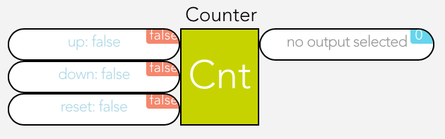
Counter
The counter can increase, decrease or reset a numerical value to 0.
The input “up” increments the counter by one when the input changes from false to true, the input “down” decrements the counter by one and “reset” resets the counter to 0.
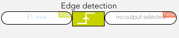
Flank Recognition
Flank recognition allows rising and falling edges to be evaluated. This means that if the selected flank appears on the input, then the output is set to true for one cycle and then reset to false.
The type of flank can be selected in the operator panel under the item “settings”.
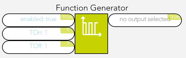
Function Generator
The function generator enables periodic square wave signals to be generated.
As soon as the input “activated” is true, the function generator is started and generates a periodic square wave signal on the output.
“TOn” can be used to adjust how long the square wave signal is true and “TOff” how long it is false.
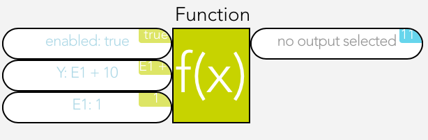
Function
A function element is used to carry out mathematical calculations. “A1” must contain the desired calculation.
The variables E1 to E6 can be used for the calculation, e.g. A1 = 2*E1 + E2.
As soon as the input “activated” is active, the calculation will be carried out. The buttons “add pin” and “remove pin” can be used to add up to 6 inputs. The following shows link shows you which operations are possible:
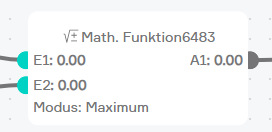
Mit dem Math. Funktionsblock können vordefinierte mathematische Berechnungen durchgeführt werden.
Folgende Funktionen stehen zur Verfügung:
Maximum: Hier können bis zu 6 Eingänge verwendet werden, von denen das Maximum ausgegeben wird
Minimum: Hier können bis zu 6 Eingänge verwendet werden, von denen das Minimum ausgegeben wird
Absolut: Gibt immer den absoluten Wert des ausgewählten Eingangs zurück
Zufallszahl: Liefert einen ganzzahligen Zufallswert zwischen dem ausgewählten Minimum und Maximum, dieser wird immer dann berechnet wenn in einem Zyklus das „Neu berechnen“ Flag auf „true“ gesetzt ist
Runden: Rundet den angegebenen Wert, hier kann zusätzlich angegeben werden auf wie viele Kommastellen gerundet werden soll
Potenzfunktion: Führt eine Potenzfunktion aus, wobei sowohl die Basis als auch der Exponent als Eingang definiert werden können
Quadratwurzel: Führt die Quadratwurzel auf den Eingang aus
Summe: Bildet die Summe aus bis zu 6 Eingängen
Mittelwert: Bildet den Mittelwert aus bis zu 6 Eingängen
Exponentialfunktion: Bildet die Exponentialfunktion zum angegebenen Exponent
Logarithmus zur Basis x: Führt den Logarithmus auf den Eingang aus, wobei die Basis angegeben werden kann
Logarithmus zur Basis e: Führt den Logarithmus auf den Eingang aus, wobei die Basis immer e beträgt
PI Controller
This is a clocked PI controller where you supply demand value, actual value and clock.
The settings for the PI controller are located in the parameter panel.
Reset
For as long as the input is true, the output of the reset element will be set to false.
SR Flip Flop
The SR flip flop is used to set and reset an output. If the input “set” is true, then the output is true. If the input “reset” is true, the output is false. If both inputs are true, then the output is false. If both inputs are false, the output is stored, meaning it remains in this state until the input is true again.
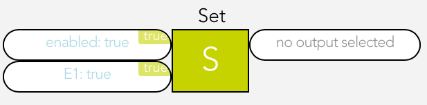
Set
For as long as the input is true, the output of the set element will be set to true.
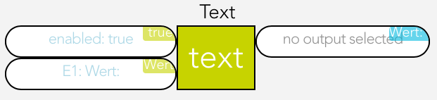
Text Block
The text block is used to create any text string you want.
1 to 6 inputs (E1 – E6) can be created using the buttons “add pin” and “remove pin” and the text from these inputs are then strung together.
For example, if the text for E1 is “It is now ” and the text for E2 is the current time (use the button “select” and under “system” then “time”), then the following text string will be created “It is now 17:00”.
Examples
WC Ventilation
Task
If the light in the WC is switched on, then the ventilation should be switched on 15 seconds later (the ventilator must be connected to a digital output) and run for one minute after the light has been switched off. If the light is switched off before the ventilator is switched on, the ventilator should not be activated.
Solution
First open the app “logic” and create a logic program via “add program”.
Give the logic program the name WC-ventilation and select the room WC.
Open the logic program via the button “edit”. Use the “add function” to add the function time relay. This relay is red, meaning that it isn’t yet working, because there are no inputs.
Now open the time relay. Since the output should be switched on after 15 seconds, you will need a delay of 15 seconds. Change the switch on delay to a fixed value and enter the value 15. Do the same for the switch off delay, except instead of 15, use the value 60, since the ventilation is only meant to run for 1 minute (= 60 seconds) after the light has been switched off.
Now you need to link inputs and outputs. Select input E1 using the button “select” and navigate to the lights, select the WC light and select “light on”. In the object panel of the time delay, you can now see the current value of the light and how it changes when the light is switched on and off. Now all you need to do is connect the output of the time relay with the digital output. To do this, click on “select” under “output” and navigate to the digital outputs. Once there, select the desired output and click on “set value”.
Now you can test your WC ventilation and see if everything is working fine.
Light Transformer
Task
There are 4 lights and 1 light transformer available. The light transformer is connected to a digital input. As soon as at least one light is switched on, the light transformer must be switched on. If no lights are switched on, the light transformer must also be switched off.
Solution
The first thing to do is open the app “logic” and create a logic program via “add program”.
Give this logic program a name “light-trans”.
Next, open the logic program using the button “edit”. Use the button “add function” to add an OR. This OR is red meaning that it is not currently functioning, because it has no inputs.
Now open the OR and add two inputs using the button “add pin”. These four inputs must now be linked with the four lights via the button “select” by selecting “light switched on” for each light. The OR is now green, because all inputs are linked. Finally, you need to connect the digital output of the transformer with the OR. Do this by clicking on “select” under “output”, open the digital output there and select “set value” for the desired digital output.
The logic should now work as desired.
Ventilation Control
Task
You measure humidity in a room and want to switch on the ventilation as soon as the humidity has reached a certain value.
Solution
To do this, the humidity sensor must be connected to an analog input of an analog module and configured accordingly (to do this, see chapter “Analog Input”). The ventilation must be connected to the output of a digital module.
Next, create a logic program in the app “logic” using “add program”. Give the program a meaningful name (e.g. fan control) and if wish, allocate a room. Then open the parameter panel and select “edit” under “edit logic”. Insert a compare function via “add function”.
Now open the operator panel of the compare function. Under the item “settings”, first select for “type” the value “greater than” (since the fan is to be switched on when the humidity is GREATER than a certain value). You can configure the hysteresis for the compare function as you feel is necessary. In this example, select 5 for the hysteresis. The sample time can be left at 0. Now the compare function is correctly configured.
The inputs and output now need to be connected. Select the analog input you connected the humidity sensor to under “inputs” for “E1”. For “E2” enter the value above which the fan is to be switched on. In this example select 80. Now select the digital output you connected the fan to using the button “select” under “output”.
The ventilation control is now complete. If you want, you can change the hysteresis and the sample time as you require.
Editor
Ab evon Smart Home Version 2.13 steht eine alternative Möglichkeit zur Bearbeitung von Logikprogrammen zur Verfügung. Die neue Logikansicht kann direkt über das Operator Panel geöffnet werden.
Upgrade bestehender Logiken
Logiken aus Versionen vor 2.13 werden beim erstmaligen Öffnen in der neuen Ansicht automatisch aktualisiert. Dabei werden einige Anpassungen vorgenommen. Nach dem Upgrade sollte das Logikprogramm überprüft werden, um sicherzustellen, dass alle Funktionen weiterhin wie erwartet funktionieren. Änderungen
Überblick
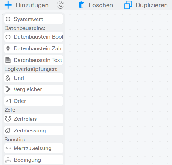
Die neue Logikansicht basiert auf einer SPS-ähnlichen Ansicht und bietet eine intuitive grafische Oberfläche zur Erstellung und Bearbeitung von Logikgruppen. Die Benutzeroberfläche besteht aus folgenden Hauptelementen:
Steuerungselemente: Buttons zum Bearbeiten, Hinzufügen, Duplizieren und Zurücksetzen der Logikgruppe. Bibliotheksbereich: Enthält alle verfügbaren Logikbausteine, kategorisiert nach Funktionsgruppen (Datenbausteine, Logikverknüpfungen, Zeitfunktionen und Sonstige). Bearbeitungsfläche: Der Hauptarbeitsbereich, in dem die Logikbausteine platziert und verbunden werden können.
Die Bearbeitungsfläche verfügt über ein Raster, das die präzise Positionierung der Bausteine erleichtert. Die Bausteine werden automatisch am Raster ausgerichtet, um eine übersichtliche Darstellung zu gewährleisten.
Bedienung des Editors
Die Logikansicht bietet zwei Hauptmodi:
Ansichtsmodus: In diesem Modus kann die Logikgruppe als Gesamtes verschoben und angesehen werden, aber keine Änderungen an den Verbindungen vorgenommen werden.
Bearbeitungsmodus: In diesem Modus können Logikbausteine hinzugefügt, verschoben, verbunden, gelöscht und konfiguriert werden.
Um in den Bearbeitungsmodus zu wechseln, kann auf den Bearbeiten-Button (Stift-Symbol) geklickt werden. Im Bearbeitungsmodus wird die Bibliothek verfügbar, und es kann mit der Erstellung oder Änderung der Logikgruppe begonnen werden.
Ansicht anpassen
Die Logikansicht bietet verschiedene Möglichkeiten zur Anpassung der Darstellung: Zoom: Mit gedrückter Strg-Taste kann mit dem Mausrad hinein- oder herausgezoomt werden. Verschieben: Die gesamten Elemente können durch Klicken und Ziehen bewegt werden. Ansicht zurücksetzen: Mit dem Zentrier-Button kann die Ansicht auf den Standardzustand zurückgesetzt werden.
Bibliothek anheften
Die Bibliothek kann im Bearbeitungsmodus dauerhaft sichtbar bleiben:
Es kann durch Klicken auf den Hinzufügen-Button (+) die Bibliothek geöffnet, anschließend durch den Pin-Button angepinnt und somit dauerhaft sichtbar gehalten werden, auch während anderer Aktionen.
Speichern und Zurücksetzen
Beim Verlassen des Bearbeitungsmodus (wieder über den Bearbeiten-Button oder über Strg+S) erscheint ein Popup und folgende Optionen stehen zur Verfügung: Speichern: Alle Änderungen werden dauerhaft übernommen. Abbrechen: Schließt das Popup und die Logikgruppe kann weiter bearbeitet werden. Zurücksetzen: Alle vorgenommenen Änderungen werden verworfen und auf den zuletzt gespeicherten Zustand zurückgesetzt.
Aufbau Logikbaustein
Jeder Logikbaustein ist einheitlich gestaltet, um eine intuitive Bedienung und schnelle Orientierung zu ermöglichen.
Visuelle Elemente eines Bausteins Kopfbereich: Zeigt das Symbol und den Namen des Bausteins zur schnellen Identifikation. Eingänge: Befinden sich auf der linken Seite und werden durch Anschlusspunkte dargestellt. Sie dienen dem Empfang von Signalen anderer Bausteine. Ausgänge: Befinden sich auf der rechten Seite und leiten Signale an andere Bausteine weiter. Statusanzeige: Im Ansichtsmodus zeigen Bausteine ihren aktuellen Status oder Wert an, was eine schnelle Funktionskontrolle ermöglicht. Fehlerhinweise: Konfigurationsfehler oder fehlende Verbindungen werden durch visuelle Hervorhebungen kenntlich gemacht.
Farb- und Textkennzeichnung der Ein- und Ausgänge
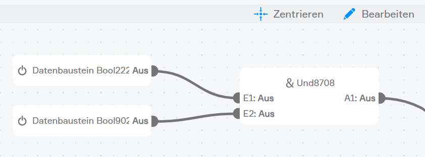
Ansichtsmodus
Im Ansichtsmodus steht eine kompakte, auf aktuelle Zustände fokussierte Darstellung mit reduziertem Funktionsumfang sowie einer Echtzeit-Anzeige aktiver Statuswerte im Vordergrund.
Für alle Ein- und Ausgänge werden Zusatzinformationen wie Invertierung und Fixwerteinstellung durch (I) bzw. -fix vor bzw. nach dem Echtzeitwert angezeigt
Boolesche Werte (wahr/falsch)
Grün oder Rot, wenn verbunden oder ein Fixwert gesetzt ist
Ausgeblendet, wenn keine Verbindung und kein Fixwert vorhanden ist
Numerische Werte
Grün: Eingang oder Ausgang ist verbunden oder ein Fixwert wurde definiert
Ausgeblendet: Keine Verbindung und kein Fixwert wurde definiert
Text-/String-Werte
Grün: Eingang oder Ausgang ist verbunden oder ein Fixwert wurde definiert
Ausgeblendet: Keine Verbindung und kein Fixwert wurde definiert
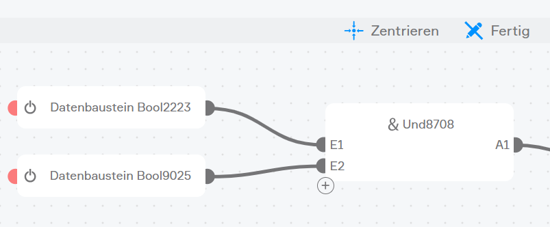
Bearbeitungsmodus
Im Bearbeitungsmodus wird eine erweiterte Darstellung mit zusätzlichen Elementen zur Konfiguration und Verbindung der Bausteine angezeigt.
Farbkennzeichnung der Ein- und Ausgänge (unabhängig vom Datentyp)
Rot: Kein Eingang oder Ausgang ist verbunden und kein Fixwert gesetzt
Grau: Eingang oder Ausgang ist verbunden oder ein Fixwert ist gesetzt
Bedienung des Logikbausteins
Logikbaustein hinzufügen
Bearbeitungsmodus aktivieren, indem auf den Bearbeiten-Button geklickt wird.
Die Bibliothek über den Hinzufügen-Button (+) öffnen.
Gewünschten Baustein aus der Bibliothek auf die Arbeitsfläche ziehen.
Der Baustein wird automatisch am Raster ausgerichtet und ist bereit zur Konfiguration.
Während des Hinzufügens zeigt ein Ladeindikator den Fortschritt an, bis der Baustein vollständig erstellt ist.
Der Systemwert-Baustein erfordert die Auswahl einer bestimmten Systemeigenschaft. In diesem Fall öffnet sich ein Auswahlfenster.
Bausteine konfigurieren
Jeder Logikbaustein außer dem Systemwert-Baustein verfügt über spezifische Eigenschaften, die konfiguriert werden können.
Auf einen Baustein klicken, um ihn auszuwählen und das Operator Panel zu öffnen.
Werte nach Bedarf anpassen. Änderungen werden automatisch übernommen.
Rechtsklick auf einen Baustein zeigt ein X-Symbol über das der Baustein gelöscht werden kann an.
Verbindungen zwischen Bausteinen erstellen
Logikbausteine kommunizieren über Verbindungen zwischen Ausgängen und Eingängen:
Auf einen Ausgang (rechte Seite) eines Bausteins klicken und die Maustaste gedrückt halten.
Die Verbindung zu einem Eingang (linke Seite) eines anderen Bausteins ziehen.
Maustaste loslassen, um die Verbindung zu erstellen.
Verbindungen werden nur hergestellt, wenn die Datentypen kompatibel sind.
Mehrfachauswahl, Duplizieren und Einfügen
Die neue Logikansicht unterstützt die Auswahl mehrerer Bausteine gleichzeitig sowie das einfache Duplizieren und Einfügen:
Maustaste lange gedrückt halten, um den Mehrfachauswahlmodus zu aktivieren.
Gewünschte Bausteine anklicken, um sie aus- bzw. abzuwählen. Ausgewählte Bausteine werden hervorgehoben.
Mit mehreren ausgewählten Bausteinen lassen sich Gruppenoperationen durchführen:
Duplizieren: Alle ausgewählten Bausteine inklusive ihrer Verbindungen können über den Duplizieren-Button (oben rechts) oder per Strg+D eingefügt werden.
Kopieren und Einfügen: Alternativ lassen sich Bausteine mit Strg+C kopieren und mit Strg+V einfügen.
Eingefügte Bausteine werden versetzt platziert und behalten ihre Eigenschaften. Bestehende Verbindungen zwischen kopierten Bausteinen werden ebenfalls übernommen.
Beispiele
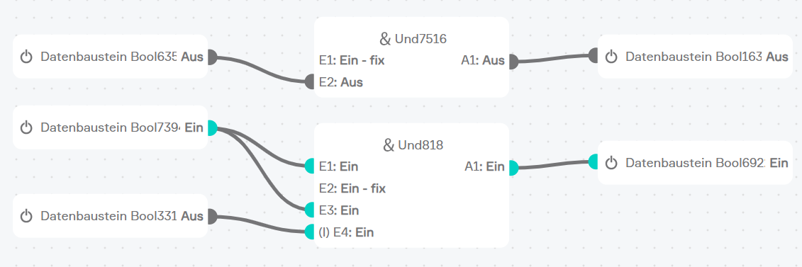
Feuchtigkeitssteuerung für das Badezimmer
Die Belüftung soll bei Überschreiten eines definierten Wertes gestartet werden.
Dazu werden 3 Bausteine benötigt.
Die Luftfeuchtigkeit des Badezimmers muss über einen Systemwert angelegt werden.
Der Ausgang dieses Werts wird mit einem Vergleicher, der im Operator Panel auf Typ größer eingestellt werden muss, verbunden. Der Vergleichswert kann entweder mit einem weiteren Nummernwert des Systems, oder wie in diesem Beispiel als Fixwert 80, definiert werden. Um kleinere Schwankungen auszugleichen wird die Hysterese auf 2 gestellt.
Weitere Informationen
Ausführungsreihenfolge
Die Ausführungsreihenfolge der Logikbausteine wird automatisch basierend auf ihrer Position in der Zeichenfläche bestimmt:
Bausteine werden von oben nach unten und von links nach rechts ausgeführt.
Die Reihenfolge kann durch Verschieben der Bausteine beeinflusst werden.
Eine korrekte Reihenfolge ist entscheidend, insbesondere bei voneinander abhängigen Bausteinen.
Fehlerbehebung und Bewährte Praktiken
Zyklische Abhängigkeiten: Verbindungen vermeiden, die zu Endlosschleifen führen können.
Fehlende Verbindungen: Alle erforderlichen Eingänge sollten korrekt verbunden sein.
Dokumentation: Aussagekräftige Namen verwenden, um die Logik nachvollziehbar zu gestalten.
Schrittweises Testen: Die Logik in einzelnen Schritten prüfen, um Fehler frühzeitig zu erkennen.
Minimale Bausteinanzahl: Nur notwendige Bausteine einsetzen.
Reduzierung unnötiger Verbindungen: Jede Verbindung erzeugt Rechenaufwand – nur relevante Verbindungen erstellen.
Update-Änderungen in der mobilen Ansicht
Es können jetzt pro Ausgang mehrere Verknüpfungen erstellt werden.